Installation
16
025-9623 D3
♦
To connect the iRIM to a computer for initial configuration
1.
Use cable 709-0065 (or a standard CAT5 Ethernet patch cable) to connect the
Network
port on the iRIM to the same network as the computer.
-or-
Use a crossover cable to connect the
Network
port on the iRIM directly to an
Ethernet jack on the computer.
♦
To connect the iRIM to DCS-5020
1.
Using either an Ethernet network or an Ethernet crossover cable (P/N 709-0130),
connect the Network Port of the iRIM to the Ethernet side of the Digi One SP
Serial-to-IP convertor.
2.
Connect the appropriate COM port of the DCS-5020 Digital Switch to the serial
side of the Digi One SP Serial-to-IP convertor. The COM port on the Digital
Switch must be properly configured. For additional information, refer to
DCS-
5020 Software Installation and Configuration
(P/N 025-9540).
♦
To connect the iRIM to Acom
1.
Using either an Ethernet network or an Ethernet crossover cable (P/N 709-0130),
connect the Network Port of the iRIM to the Acom EIU. For more information,
refer to
Acom Ethernet Interface Unit
(P/N 025-9620).
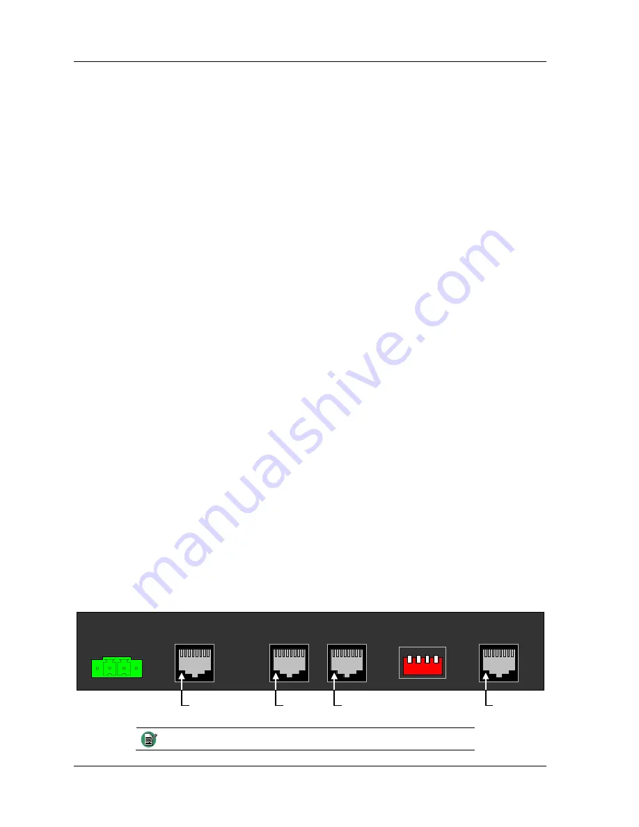
Consoles Port
To connect the radio audio to DCS-5020, use the supplied Y-cable (P/N 709-7881) to
connect the
Consoles
jack on the back of the iRIM to the
RMT
jacks on the Basic Dual
Radio Module in the DCS-5020 Digital Switch.
To connect the radio audio to Acom, use the supplied standard RJ-45 cable wired for
Ethernet (P/N 209-0065) to connect the
Consoles
jack on the back of the iRIM to the
Acom system’s punchdown block. These wires ultimately connect to either an RIU or an
EIU card. This single cable carries transmit and receive pairs for both radio channels.
Since the interface uses differential audio, it is important that the twisted pairs in the
cable correspond to the audio pairs on the connector.
information.
Figure 5: iRIM Rear Panel
+13.5VDC/GND
A B C D
Consoles
Network
Radio B
Radio A
Pin 1
Pin 1
Pin 1
Pin 1
Note
This table assumes the cable follows the T-568B wiring scheme.


