background image

LAP-F1 Logic Analyzer 

User Guide v1.6 

|    www.zeroplus.com.tw 


118


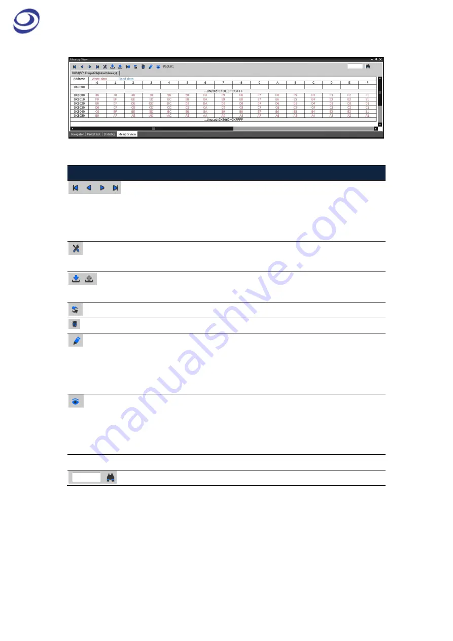
Figure 4-69 Memory View window showing an SPI protocol 

Item 

Description 


Navigation buttons: Move between packets. The packet in focus will be 

in the middle of the waveform view area and marked by the reaction 

bar (A-bar by default). The packet data will be displayed in the 

Memory View window. 


Options; See Table 4:47 Memory View options dialog box description 


Import/Export/Merge: Users can import, export or merge .txt and .csv 

file for display in the Memory View or another software. 


Refresh. 


Reset: Delete the data in the Memory View window. 


Write Operation: The last written data will be shown in the cells as red 

text on white background. If there is incongruence between read and 

written data to the same address then errors will be shown on yellow 

background.   


Read Operation: The last read data will be shown in the cells as blue 

text on white background. If there is incongruence between read and 

written data to the same address then errors will be shown on yellow 

background.   

Packet 

Show the number of the packet where the reaction bar is located. 


Find: Input an address to look it up and highlight it with a blue frame. 

Table 4:46 Memory view description 

Summary of Contents for LAP-F1

Page 1: ...LAP F LOGIC ANALYZER USER GUIDE V1 7 June 2016...

Page 2: ...duction 17 1 4 Package Content 17 1 5 System Requirements 18 1 6 Product Specifications 19 2 Installation and Setup 25 2 1 Software Installation 25 2 2 Hardware Setup 26 2 3 Connection to DUT 28 2 4 e...

Page 3: ...Channel 59 4 15 Add Bus 60 4 16 Add Protocol Decoder 63 4 17 Acquisition Setup 66 4 18 Trigger Setup 73 4 19 Trigger Options 76 4 20 Trigger Level 77 4 21 Protocol Trigger 77 4 22 Single Capture 78 4...

Page 4: ...C Event Trigger 100 4 42 I O Delay 101 4 43 Long time Record 102 4 44 Channel Folding 103 View 105 4 45 Menu Layout 105 4 46 Cursor Type 105 4 47 Display Type 106 4 48 Refresh 114 4 49 Zoom 115 4 50 C...

Page 5: ...LAP F1 Logic Analyzer User Guide v1 6 www zeroplus com tw 5 4 61 Menu Layout 132 4 62 About ZP Logic 133 4 63 About Zeroplus 133 4 64 Help 133 4 65 Hot Keys 134 4 66 Send Feedback 137 5 Contact Us 140...

Page 6: ...bes 29 Figure 2 7 eMMC probe tuning screw 30 Figure 3 1 ZP Logic user interface 33 Figure 3 2 Reposition hide sector right click menu 34 Figure 3 3 Repositioning the Control Panel example 35 Figure 4...

Page 7: ...4 Figure 4 20 Acquisition Setup dialog box 66 Figure 4 21 Trigger Level dialog box for Low Voltage Probes 68 Figure 4 22 Connection diagram with LAP F1 as master 69 Figure 4 23 Connection diagram with...

Page 8: ...waveform example A0 AND A1 93 Figure 4 43 Noise Filter dialog box 94 Figure 4 44 Draw Analog Waveform dialog box 95 Figure 4 45 Draw Analog Waveform example 96 Figure 4 46 Real time frequencies window...

Page 9: ...es is displayed inside the traces 117 Figure 4 69 Memory View window showing an SPI protocol 118 Figure 4 70 Memory View options dialog box 119 Figure 4 71 Navigator window example showing the AC97 pr...

Page 10: ...83 Statistics Highlight signals dialog box 128 Figure 4 84 TLR Monitor window 128 Figure 4 85 Find Results dialog box 129 Figure 4 86 Find Results example 130 Figure 4 87 Timing Bar 130 Figure 4 88 H...

Page 11: ...22 Table 1 10 LAP F1 input ports 23 Table 2 1 General advices for cleaning operation and storage 32 Table 3 1 UI description Area refers to the letter codes on the figure above 34 Table 3 2 Reposition...

Page 12: ...4 18 DSO Connection dialog box description 72 Table 4 19 Supported oscilloscope models 72 Table 4 20 DSO driver needed for the DSO connection 73 Table 4 21 Trigger Setup dialog box description 75 Tab...

Page 13: ...111 Table 4 41 State List example change of channel state 113 Table 4 42 State List view right click menu in the number area 113 Table 4 43 Channel Bus State List view right click menu description 11...

Page 14: ...www zeroplus com tw 14 Table 4 51 Available data formats 132 Table 4 56 Hot Key descriptions 137 Table 4 57 Send Feedback dialog box description 139 Table 5 1 Sales department contact info 140 Table 5...

Page 15: ...t recommendations from Table 2 1 Protect the LAP F1 from static discharge Avoid direct impacts and rough handling The LAP F1 is an IEC 61010 1 Level 2 instrument The relevant pollution caution is Norm...

Page 16: ...u for purchasing the LAP F1 logic analyzer Zeroplus is short for Zeroplus Technology Co Ltd 1 2 About this document This User Guide is organized as follows First the characteristics of the LAP F1 are...

Page 17: ...nctions make debugging a joy All of these functions are described in chapter 4 1 4 Package Content All items contained in the LAP F1 package are listed in Table 1 1 If any of the items is missing or d...

Page 18: ...Windows 8 1 32 and 64 bit Recommended Windows 7 32 and 64 bit Windows Vista 32 and 64 bit Windows XP 32 bit Home Professional Editions Windows 2000 Professional Server series Table 1 2 Supported opera...

Page 19: ...Table 1 2 Acquisition Channels 40 or 64 Interface USB 3 0 2 0 compatible Sampling Frequency Internal Timing 1 GHz External State 200 MHz Dual edge Memory channel 4 8 16 32 64 Mb Trigger Trigger Chann...

Page 20: ...distant parts of the waveform Memory View See what the memory looks like what is read written to each address Packet List Breakdown of all packets in list form Statistics Table view of number of perio...

Page 21: ...Long Time Record This function is used to stream samples directly to disk The speed can reach 300MB s using USB 3 0 The Long Time Record function can be used to acquire signals for 7 hours to 35 days...

Page 22: ...Item TTL Negative Logic eMMC SD Code P100TL P120NE P200EM Incl in base purchase Yes No 4 incl Signal Type Single ended Single ended Single ended Channels Max 64 64 32 Input Impedance 530 kohm 10 190 k...

Page 23: ...AG 1 Case by case usage sits below the CLK IN port STACK 1 Stack multiple instruments to increase channel count not currently available TRIG OUT 1 Connect to DSO for external triggering see chapter 4...

Page 24: ...LAP F1 Logic Analyzer User Guide v1 6 www zeroplus com tw 24 Figure 1 3 Cable connections to the LAP F1...

Page 25: ...o the PC via USB Insert the ZP Logic Software CD into the CD ROM If the CD does not auto play open the set exe file manually The dialog box from Figure 2 1 will be shown Figure 2 1 Main installation w...

Page 26: ...is recommended to do so When the ZP Logic is launched for the first time a Find New Hardware dialog box will appear and the driver will then be installed automatically ZP Logic will also download all...

Page 27: ...the instrument see Figure 2 4 Figure 2 4 Test cables connected to the LAP F1 Connect the LAP F1 to the PC using the USB then power up the instrument to ensure that it s working Connect the AC power c...

Page 28: ...nal quality These characteristics make the probes well suited for high speed signal measurements Each active probe provides two channels and consists of four cables two signal cables and two ground ca...

Page 29: ...ad type and active NOTE Each signal ground pair of cables is glued in one end and flies in the other If the ground pins are not conveniently positioned on the DUT it is possible to turn the cable pair...

Page 30: ...and Negative Logic probes are adjusted as described in chapter 4 17 1 Figure 2 7 shows an eMMC probe Turn the tiny screw as explained in the steps below to adjust the Trigger Level Figure 2 7 eMMC pro...

Page 31: ...rigger conditions have been met the LAP F1 can emit a signal that can be used to trigger another instrument This signal can be sent on the occurrence of three different events these are detailed in Ta...

Page 32: ...rature Working Min 5 C Max 35 C Temperature Storage Min 20 C Max 60 C Rel humidity Working Min 20 Max 85 Rel humidity Storage Max 90 Altitude Max 2 000 m Insolation Avoid direct sunlight Environment U...

Page 33: ...u A All operations can be accessed from the Main Menu bar The organization of chapter 4 corresponds to that of the Main Menu see chapter 4 for details Quick Access Toolbar B The Quick Access Toolbar p...

Page 34: ...see Figure 4 67 for more details Table 3 1 UI description Area refers to the letter codes on the figure above NOTE The Control Panel and the Secondary Display can be repositioned or hidden Right click...

Page 35: ...yzer User Guide v1 6 www zeroplus com tw 35 repositioned to the corresponding transparent blue area in the example the user is holding the mouse over the upward arrow Figure 3 3 Repositioning the Cont...

Page 36: ...f by showing the corresponding drop down menu from the Main Menu The functions are presented one by one in the succeeding subchapters NOTE ZP Logic will automatically check online for updates upon sta...

Page 37: ...TRL F4 4 5 Save Save the active file If the file has not been saved before the Save As dialog box will open see chapter 4 6 Hot Key CTRL S 4 6 Save As Save As is useful for users who wish to save a fi...

Page 38: ...o try to save a file or initiate certain other functions will be informed that the acquired data needs to be processed to proceed This setting is accessed under General in the Options dialog box as Au...

Page 39: ...ption File name Input the file name the default is Wave Save as type Save the file as txt or csv the default is txt Include environment info Include acquisition parameters etc in the export file check...

Page 40: ...ta for timestamp X only if at least one data has changed state from timestamp X 1 to timestamp X for buses only Bus Selection Select buses to be included in the export file Range From To Select the ra...

Page 41: ...53 for more details on the Packet List function itself The Export Packet List dialog box is shown in Figure 4 3 Figure 4 3 Export Packet List dialog box Item Description File name Input a file name th...

Page 42: ...port Settings Include environment info Include acquisition parameters etc in the export file checked by default Include packet names Include packet titles in the export unselected by default Open file...

Page 43: ...e as type Export in txt csv or bin format the default is txt Export Settings Available for bin exports Fill empty data bytes with Fs Fill empty spaces with the letter F selected by default Fill empty...

Page 44: ...ialog box Item Description Capture to File Save the captured region in bmp or jpeg format Clipboard Copy the captured region to the clipboard for editing in other software MS Paint Open the captured r...

Page 45: ...art of the waveform or state list that is viewed at the moment of printing The Timing Bar above the waveform and the Channel Column with the trigger conditions is also printed The Waveform State List...

Page 46: ...n of multiple copies Ex 2 copies of 3 pages will print 1 2 3 1 2 3 when collate is checked default option and 1 1 2 2 3 3 when unchecked Table 4 5 Print Setup dialog box description 4 10 Print Preview...

Page 47: ...s option governs the software behavior when the user presses Stop in the middle of an acquisition If this option is selected then the previous acquisition will be displayed again Show newly acquired d...

Page 48: ...bination of packet size and zoom level Keyboard Open an on screen keyboard when inputting numbers The on screen keyboard is operated with the mouse by default it is not shown PageSize PageSize relates...

Page 49: ...ogic starts selected by default Round inputs up down to nearest valid number Illegal input values are automatically rounded to the nearest valid value selected by default Show Tips on Hovering Quick A...

Page 50: ...roups ZP Logic comes with pre defined groups a Standard group and one group for each of the Main Menu items The Standard group consists of a selection of common functions the second type provides shor...

Page 51: ...r the mouse cursor does not hover over it this option is unchecked by default Large Icons Set the icon size to 32x32 px the default size is 24x24 px Table 4 8 Quick Access Toolbar dialog box descripti...

Page 52: ...Time Add Channel Bus Waveform DSO Connection State List Active Range Real time Frequencies Noise Filter Navigator Files Comparison Packet List Previous Difference Statistics Next Difference Memory Vi...

Page 53: ...olors Users can customize the colors of bars texts traces and other elements of the user interface To change the color of an element click the corresponding color bar in the Color column of the dialog...

Page 54: ...es are shown in black and white Contrast All traces are displayed in colors that contrast the background Table 4 10 Color settings dialog box description 4 11 5 Waveform The appearance of the traces a...

Page 55: ...oose between saw tooth and square shaped traces Ruler Mode Fixed The center of the screen is fixed at 0 sec Samples Time Second is defined as the trigger event this is the default option Bar Snap to e...

Page 56: ...n or single key and click Assign to make the change effective Current Keys Displays the current Hot Keys for the selected command Conflict Keys If the new Hot Keys are already in use the command curre...

Page 57: ...tings Administrator My Documents ZP Logic Data if C is the system disk Save Options Save acquisitions automatically Auto save all acquisitions Keep time from first save increment version number only W...

Page 58: ...th 2015 becomes ZP Logic_20150825 1 File Name Time File Version Add the time Hour Minute Second and the version number after the file name Ex 13 45 02 pm becomes ZP Logic_134205 1 default selection Fi...

Page 59: ...d and bring them over to the right column using the arrow The CTRL and SHIFT keys can be used to mark several channels at the same time Using the lower arrows channels can also be removed To finalize...

Page 60: ...t the dialog box differs slightly see Figure 4 16 First it links to the Advanced Settings dialog box see Figure 4 17 Second the right most column indicates which is the most significant bit and which...

Page 61: ...LAP F1 Logic Analyzer User Guide v1 6 www zeroplus com tw 61 Figure 4 16 Add Bus dialog box...

Page 62: ...l and Event The Latch function is used to analyze decode bus activity that does not use a specific protocol referred to simply as a Bus in ZP Logic When selecting a channel and an event for instance A...

Page 63: ...4 16 Add Protocol Decoder Select the desired Protocol Decoder from the dialog box shown in Figure 4 18 The protocol decoders are arranged by industry in a list where each section can be collapsed expa...

Page 64: ...shown in Figure 4 19 is an example that shows the I2C decoder setup Note that all protocol decoder dialog boxes have distinct designs Figure 4 19 I2C Protocol Decoder Setup dialog box Table 4 15 list...

Page 65: ...ial Wire Debug SWD DIGITAL LOGIC MCU 51 DECODE SHT11 DigRF MDDI SIGNIA 6210 DM114 DM115 MHL CBUS SLE4442 DMX512 MICROWIRE SMBus 2 0 DP AUX Channel MICROWIRE EEPROM 93C SPI DS1302 MIDI SPI PLUS DS18B20...

Page 66: ...g box see Figure 4 20 below This is also where users can adjust the voltage threshold for triggering and configure a DSO connection Figure 4 20 Acquisition Setup dialog box Item Description Acquisitio...

Page 67: ...cted to each of the channel ports of the LAP F1 and each probe samples one signal By default Port A0 Probe0 is linked with channel A0 in the software etc Channels can be renamed and rearranged The lef...

Page 68: ...the Trigger Level See the dialog box in Figure 4 21 Figure 4 21 Trigger Level dialog box for Low Voltage Probes Item Description Probe Type For LAP F1 All currently available probe types TTL Low volta...

Page 69: ...on modes are possible the connection can be set up with LAP F1 as master or slave depending on which instrument the user wants to provide the trigger signal The two modes are described in continuation...

Page 70: ...occurs the DSO sends a trigger signal to the LAP F1 which upon receiving the signal starts to store data See the complete connection diagram in Figure 4 23 Users can try to connect the DSO Trigger Ou...

Page 71: ...Div to 2mV Div in a total of 11 steps Options Show DSO signal only Choose which DSO signals to display in the waveform area and their colors DSO_Ch1 4 Heights DSO_Ch1 4 Set the trace height in pixels...

Page 72: ...Scope 3206B Series USB GwInstek GDS 1000A Series USB GDS 3000 Series USB Agilent DSO5000 Series USB BK Precision 2540B 2542B 2540B GEN 2542B GEN USB RIGOL DS4034 USB Table 4 19 Supported oscilloscope...

Page 73: ...ion Group 0 Port A B and Group 1 Port C D The first 16 channels are sampled by ports A0 15 Group A the next 16 in ports B0 15 Group B etc For the 40 channel LAP F1 model all ports from channel C9 to D...

Page 74: ...on Wait is disabled default option Set As Previous Level Copy the trigger conditions from the previous level Default Reset the level to default Pulse widths and Intervals Enable Interval Time Interval...

Page 75: ...rigger event occurs before the pre trigger data requirement has been fulfilled If unchecked default option the LAP F1 will override the Trigger Position Sample Depth requirement and start storing data...

Page 76: ...tions dialog box Item Description Trigger Delays Trigger Page Data Page Each time acquisition as a page Input trigger page by case Trigger Delay Trigger a certain time or a certain amount of clock cyc...

Page 77: ...time Record function set the number of continuous trigger times Table 4 22 Trigger Options dialog box description 4 20 Trigger Level See chapter 4 17 1 4 21 Protocol Trigger The Protocol Triggers are...

Page 78: ...nstructed condition set Table 4 23 Protocol Trigger dialog box description 4 22 Single Capture Capture samples one time using the current Acquisition Settings and Trigger Conditions Hot Key F5 4 23 Re...

Page 79: ...be restarted LAP F1 will then restart acquisitions until the limit is reached 1 65 536 times is available 10 times is the default option Time Choose how long in time the acquisitions should be restart...

Page 80: ...e keyboard 4 26 Menu Layout Figure 4 29 Analysis drop down menu 4 27 Active Range Adjust the analysis range by adjusting the position of the so called Ds and Dp bars The Ds bar marks the beginning of...

Page 81: ...r the waveform view on the A bar B bar Default bar intended for navigation and measurement that the user can move freely Press B to center the waveform view on the B bar Table 4 25 Description of the...

Page 82: ...he same as repositioning the bar To center the display on the T bar press T and correspondingly for the A and B bars To focus on user defined bars use the number keys To focus on for example the D1 ba...

Page 83: ...hannel Choose the need to find the channel bus or Protocol Decoder Find Options Set The search conditions The available The conditions are Rising Edge and Falling Edge or Either Edge Find Range Set to...

Page 84: ...n menu The waveform area will center on the selected bar If there are several bars of type A A0 A1 A2 etc then click next to move from one bar to the next The A bar is the default choice It is also po...

Page 85: ...hown 4 31 Highlight Data Highlight Data colors data that satisfies a user defined condition to make them stand out See the dialog box in Figure 4 34 Figure 4 34 Highlight Data dialog box Item Descript...

Page 86: ...is are highlighted with an orange color Had the function not been used these data would have had the same white background color as the neighboring 0X1 data Figure 4 35 Highlight Data example packets...

Page 87: ...red to the Reference File When contrasting with None the Reference File settings will be used to make an acquisition Settings Start Select where to start the Files Comparison using the reference file...

Page 88: ...parison Note that this function needs to pre process a temporary file see note in chapter 4 6 Statistics Results Display the status of channels contrast PASS means the data in the channel is identical...

Page 89: ...7 SEGMENT LED LCD12864 LCD1602 etc Captured data that are decoded with one of the supported protocols are decoded and displayed as the original picture This makes for a painless and straightforward v...

Page 90: ...eration function users can create a new signal through one the following arithmetic operations Add Subtract Multiply or Divide ZP Logic only accepts the creation of one arithmetic trace at a time Figu...

Page 91: ...an ADD operation on signals A0 and A1 Figure 4 40 Arithmetic operation example ADD A0 and A1 4 34 2 Boolean Operation With the Boolean operation users can create a new signal using one of the Boolean...

Page 92: ...s second signal to be XX to the first one Boolean Operator The available Boolean operators are AND OR NAND NOR XOR XNOR and NOT NOT takes only one argument and inverts it Output Name Input a name for...

Page 93: ...the dialog box in Figure 4 43 After activating the Noise Filter users select one or more channels to be filtered and move them to the right column using the right pointing arrows To select two or more...

Page 94: ...aveform The Draw Analog Waveform function is used to plot traces based on the value of bus data It is especially useful for data that can be conveniently displayed visually such as an ADC output repre...

Page 95: ...ult option Mixed Analog Display Show the drawing on top of the traces its based on Signed Setting Unsigned Binary data are read as unsigned default option Signed Binary data are read as signed Table 4...

Page 96: ...are seeing Two modes are available Real time Frequencies and Signal Status By means of these functions the LAP F1 monitors signal frequencies and states thus assuming the function of a frequency count...

Page 97: ...be performed when the Real time Frequencies window is open Also at least two periods must be captured for the function to work 4 37 2 Signal Statuses The Signal Statuses window shows another view of...

Page 98: ...Logic Analyzer User Guide v1 6 www zeroplus com tw 98 Figure 4 47 Signal Statuses window Options Press ALT O to open this Main Menu item with the keyboard 4 38 Menu Layout Figure 4 48 Options drop dow...

Page 99: ...ure 4 49 for the eMMC display setup dialog box These settings can be changed both before and after acquisitions NOTE To fully decode and trigger on all 11 eMMC signals users must purchase the optional...

Page 100: ...Purchasing the optional full eMMC5 1 and SD3 0 decoding capability the user will unlock 32 channels for 2 GHz sampling to fully trigger and decode all the signals of eMMC5 1 SD3 0 As eMMC only has 11...

Page 101: ...correct eMMC timing skew Figure 4 51 I O Delay dialog box Item Description Post Calibration This option is used to adjust timing skew post acquisition Input Delay This option is used to adjust timing...

Page 102: ...ver USB3 0 thus allowing much longer acquisitions than during normal operations when the samples are stored in the LAP F1 s internal memory The LTR function is perfect for as an example burn in tests...

Page 103: ...LTR function NOTE While running the LTR function it is recommended that the PC is not used for anything else 4 44 Channel Folding This optional function is available for the LAP F1 Channel Folding is...

Page 104: ...tivate the channel and click green empty boxes to activate channels Current used channels Number of channels that have not been deactivated The max memory of each channel Shows the memory available pe...

Page 105: ...movement in the waveform is achieved with the mouse wheel Hot Key SPACE the cursor mode changes temporarily when the user presses and holds the SPACE bar 4 46 1 Pointer In Pointer mode the left mouse...

Page 106: ...ft mouse button is used for panning click and hold the left mouse button to move left and write in the waveform area To move a bar left click on the bar name and drag sideways 4 47 Display Type The me...

Page 107: ...Add Bar Add a bar see chapter 4 28 1 Reposition A bar Reposition the A bar to the cursor location Hot Key SHIFT A B bar Reposition the B bar to the cursor location Hot Key SHIFT B Ds bar Reposition th...

Page 108: ...eft click with the mouse can be combined with pressing and holding SHIFT to select several channels or with CTRL to select a range of channels Hot Key CTRL C Paste Paste the copied channel s or bus es...

Page 109: ...Default Restore all Bus Channels settings to default Table 4 38 Channel column right click menu description NOTE Move the cursor to the bottom line of channel the cursor will turn into an icon showing...

Page 110: ...o low Either Edge Trigger on a change of state of the signal either from 0 to 1 low to high or from 1 to 0 high to low Default Reset the trigger conditions of all channels Table 4 39 Trigger column ri...

Page 111: ...omments can be maximum 10 characters long Table 4 40 Bar right click menu description NOTE The T bar has no right click menu NOTE The A bar B bar Ds bar and Dp bar cannot hold comments or be deleted F...

Page 112: ...r in data Table 4 41 shows an example of how this works Samples 1 2 and 3 are shown if the user views all samples If the user chooses to show changes in state only then Sample 2 will be hidden as all...

Page 113: ...cursor position Ds and Dp bar Reposition the Ds or Dp bar to the cursor position This option is only available if Active Range has been activated More Bars Reposition another bar to the cursor positi...

Page 114: ...ew right click menu Item Description Add Protocol Decoder Add a protocol decoder see chapter 4 16 Protocol Decoder Properties Set the protocol decoder properties see chapter 4 16 This menu item is onl...

Page 115: ...iew area Hot Key CTRL ALT P 4 49 4 Previous Cancel the last zoom In other words go back to the previous zoom level Hot Key CTRL Z 4 49 5 Cancel Previous Undo the previous zoom command Hot Key CTRL Y 4...

Page 116: ...to pre trigger data and 90 to post trigger data Action Wheel See Figure 4 67 and Table 4 45 Table 4 44 Control Panel description Figure 4 67 Action Wheel Item Description A Cursor type Switch between...

Page 117: ...p between data and addresses in a protocol is clarified The Memory View window is located in the Secondary Display Area Concretely the Memory View window consist of tables that show which data have be...

Page 118: ...he Memory View or another software Refresh Reset Delete the data in the Memory View window Write Operation The last written data will be shown in the cells as red text on white background If there is...

Page 119: ...ed range 16 is default Color Change the color settings Table 4 47 Memory View options dialog box description 4 52 Navigator The Navigator is a condensed form of the main waveform that is always zoomed...

Page 120: ...r window example showing the AC97 protocol 4 53 Packet List The Packet List shows all the acquired packets in their decomposed form By presenting the packets in list form the Packet List facilitates o...

Page 121: ...e top of the Packet List The data is highlighted with a red frame when found see Figure 4 73 This also can search string Input a string to find and it would be displayed the first packet of String at...

Page 122: ...t Select the items to be displayed and their colors Name Include the names of the packets Timestamp Packet timing the first being defined as zero Time Difference Time difference from packet X to packe...

Page 123: ...eform is centered on that packet On the contrary double click the waveform of a packet the packet list also jumped to the location of the packet Synchronize Packet List and Waveform navigation When pa...

Page 124: ...king in the Packet List Figure 4 77 Packet List Right click menu Item Description Hide Hide the current selection of packets Display Display the hidden packets Color Change the packet color Ascending...

Page 125: ...of positive and negative periods in a specific time range The Statistics window facilitates counting of signal transitions for each channel Specifically Full Positive and Negative periods are all coun...

Page 126: ...alog box in Figure 4 81 Filter only count periods that fit the filter conditions This function is not activated by default see the dialog box in Figure 4 82 Highlight signals mark channels that don t...

Page 127: ...LAP F1 Logic Analyzer User Guide v1 6 www zeroplus com tw 127 Figure 4 80 Statistics Channel selection dialog box Figure 4 81 Statistics Customize dialog box...

Page 128: ...box Figure 4 83 Statistics Highlight signals dialog box 4 55 LTR Monitor The LTR Monitor window is used to monitor the data transfer between the DUT and the computer when using the Long term Record f...

Page 129: ...ites data Min Write Rate The minimum rate at which the LAP F1 can write data Max Write Rate The maximum rate at which the LAP F1 can write data Recorded Data Data quantity currently acquired Loss of d...

Page 130: ...example 4 57 Timing Bar Figure 4 87 Timing Bar Item Description Scale The scale is the inverse of the zoom level Total Total acquisition time Waveform Center Location of the current center of the wav...

Page 131: ...the waveform area Table 4 54 Timing Bar description 4 58 Arrange Windows The windows showing the files as waveforms or as lists of states can be moved around freely 4 58 1 Horizontal Display the open...

Page 132: ...ary Data are shown using the binary number system Decimal Data are shown using the decimal number system Decimal Signed Data are shown using the signed decimal number system one bit the first on the l...

Page 133: ...w shown the first time the ZP Logic is started Figure 4 89 About ZP Logic information window 4 63 About Zeroplus The About Zeroplus item on the menu takes the user to the Zeroplus website this is open...

Page 134: ...ns of the dialog box fields Command Hot Keys Description File New Ctrl N Create a new file File Open Ctrl O Open an exit file File Close Ctrl F4 Close the current file File Save Ctrl S Save the file F...

Page 135: ...Whole page mode Recovery zoom Ctrl Z Return to the last zooming Cancel zoom Ctrl Y Cancel the last zooming Help Help F1 Open the operating instructions of Zeroplus Logic Analyzer Go to A bar A Move A...

Page 136: ...the previous memory page Next page Ctrl Page Down Go to the next memory page First page Ctrl Home Go to the first memory page Last page Ctrl End Go to the last memory page Previous view Page Up Go to...

Page 137: ...rm the menu command or command of other baseline Show waveform Wheel Move the waveform First channel Ctrl Select the first channel Last channel Ctrl Select the last channel Previous channel Shift Sele...

Page 138: ...e information instrument model acquisitions settings system parameters etc This information makes it easier for the support team to get to the root of the problem and therefore improves response times...

Page 139: ...one Sender s phone number Subject Sender s brief description of the issue Attachment Relevant files graphs etc can be attached to the form Content Elaborate a written description of the issue Paramete...

Page 140: ...tact Us Sales Department Email service_1 zeroplus com tw Phone 886 2 6620 2225 extension 221 or 311 Table 5 1 Sales department contact info Technical Support Email service_2 zeroplus com tw Phone 886...

Reviews: