background image


             inBOX 24 / inBOX 20


http://www.zennio.com


Technical Support:


http://support.zennio.com


11 

mode. After that, an  additional press will turn the LED yellow and then off, 

once the button is released. This way, the device leaves the Test On mode. 

Note that it will also leave this mode if a bus power failure takes place

Test Off Mode 

Under the Test Off  Mode, the outputs can be controlled through both their 

communication objects and the actual pushbuttons located on the top of the device.  

When one of these buttons is pressed, the output will behave as if an order had been 

received through the corresponding communication object, depending on whether the 

output is configured as an individual output or as a shutter channel. 


Individual output

: a


simple press (short or long) will make the output switch 

its on-off state, which will be reported to the KNX bus through the 

corresponding status object, if enabled. 


Shutter Channel

: when the button is pressed, the device will act over the 

output according to the length of the button press and to the current state. 

  A 

long press

  makes the shutter start moving (upwards or downwards, 

depending on the button being pressed). The LED will light in green  until 

the end of the motion. If the button gets pressed being the shutter already 

at the top or bottom positions, nothing will happen (the LED will not light). 

  A 

short press

 will make the shutter drive stop (if in motion), as it normally 

does when a step/stop order is received from the KNX bus. In case of not 

being the shutter in motion, pressing the button does not cause any action, 

unless slats/lamellas have been parameterized  –  in such  case, a step 

movement (up/down, depending on the button pressed) will take place. 

The status objects will be sent to the bus when corresponding.  


Disabled output

: outputs disabled by parameter will not react to button 

presses under the Test Off mode. 

Regarding the lock, timer, alarm and scene functions, the device will behave under the 

Test Off mode as usual. Button presses during this mode are entirely analogous to the 

reception of the corresponding orders from the KNX bus. 

Summary of Contents for ZIO-IB24

Page 1: ...inBOX 24 inBOX 20 Multifunction Actuator for Flush Mounting ZIO IB24 USER MANUAL ZIO IB20 Application program version 1 0 User manual edition 1 0 _a www zennio com...

Page 2: ...nstallation 4 1 3 Start Up and Power Loss 5 2 Configuration 6 2 1 General 6 2 2 Inputs Only inBOX 24 8 2 2 1 Binary Input 8 2 2 2 Temperature Probe 9 2 2 3 Motion Detector 9 2 3 Outputs 10 2 3 1 Manua...

Page 3: ...e 2 relay outputs configurable as 1 shutter channel with or without slats or Up to 2 individual ON OFF outputs 4 multi purpose inputs configurable as Temperature probes Binary inputs i e pushbuttons s...

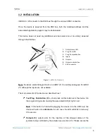
Page 4: ...ly analogous for inBOX 20 although the inputs are not available The main elements of the device are described next Test Prog Pushbutton 3 a short press on this button sets the device into the programm...

Page 5: ...ce and also available at www zennio com 1 3 START UP AND POWER LOSS During the start up of the device the Test Prog LED will blink in blue colour for a few seconds before the device is ready External...

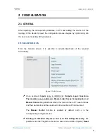
Page 6: ...ate deactivate all the required functionality Figure 2 Default screen Once activated Inputs only in inBOX 24 Outputs Logic Functions Thermostats only in inBOX 24 Master Light Scene Temporisation and M...

Page 7: ...It is possible to parameterise a certain delay to this sending 0 to 255 seconds Figure 3 Sending of Indication objects on bus voltage recovery Heartbeat Periodical Alive Notification this parameter l...

Page 8: ...IO DETEC X from Zennio Important older models of the Zennio motion detector e g ZN1IO DETEC and ZN1IO DETEC N will not work properly with inBOX 24 ETS PARAMETERISATION When Inputs has been activated i...

Page 9: ...r available in the inBOX 24 product section at the Zennio website www zennio com Notes The ZN1IO DETEC P motion detector is compatible with a variety of Zennio devices However depending on the device...

Page 10: ...re available per output Manual operation can be done in two different ways named as Test On Mode for testing purposes during the configuration of the device and Test Off Mode for a normal use anytime...

Page 11: ...he device will act over the output according to the length of the button press and to the current state A long press makes the shutter start moving upwards or downwards depending on the button being p...

Page 12: ...position of the shutter and the parameterised times Note after leaving the Test On mode the status objects will recover the values they had prior to entering Test On As the device is never aware of t...

Page 13: ...ecial action while switching to the Test On mode does require long pressing the Prog Test button Lock Manual Control unless the above parameter has been Disabled the Lock Manual Control parameter prov...

Page 14: ...ution of each function can depend on a configurable condition which will be evaluated every time the function is triggered through specific parameterisable communication objects The result after execu...

Page 15: ...implements four Zennio thermostats which can be enabled and configured independently Please refer to the specific Zennio Thermostat user manual available in the inBOX 24 product section at the Zennio...

Page 16: ...to the KNX bus in both cases a shutter order a thermostat setpoint or mode switch order a constant value a scene Only the trigger object and the twelve status objects are required to be binary on off...

Page 17: ...takes off Scene if checked object ML General Switch off Scene will be enabled which will send a scene run save order configurable in Action and Scene Number whenever the general switch off takes off...

Page 18: ...tp support zennio com 18 when the courtesy switch on takes place in contrast to object ML General Switch Off Binary Object which sends the value 0 during the general switch off as explained above Figu...

Page 19: ...ing for that output or that channel such temporisation will be interrupted and only the delay and the action of the new scene will be executed ETS PARAMETERISATION Prior to setting the scene temporisa...

Page 20: ...e scene temporisation Therefore parameter Scene m Z Delay defines the delay that will be applied to the action defined in Z for the execution of scene m where Z may be a specific individual output shu...

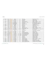
Page 21: ...ta Entry x 1 byte Data Entry 0 255 53 68 2 Byte I C W DPT_Value_2_Ucount 0 65535 LF 2 bytes Data Entry x 2 bytes Data Entry DPT_Value_2_Count 32768 32767 DPT_Value_Temp 273 00 670760 00 69 76 4 Byte I...

Page 22: ...105 1 Bit I C W DPT_UpDown 0 1 CA Move 0 Raise 1 Lower 106 1 Bit I C W DPT_Step 0 1 CA Stop Step 0 Stop StepUp 1 Stop StepDown 1 Bit I C W DPT_Trigger 0 1 CA Stop 0 Stop 1 Stop 107 1 Bit I C W DPT_Ena...

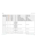
Page 23: ...Door 0 1 Tx Window Status input 0 Closed 1 Open 132 162 192 222 1 Bit I C W DPT_Trigger 0 1 Tx Comfort Prolongation 0 Nothing 1 Timed Comfort 133 163 193 223 1 Byte O C T R DPT_HVACMode 1 Comfort 2 St...

Page 24: ...us Object 5 Binary Status 249 1 Bit I C W DPT_Switch 0 1 ML Status Object 6 Binary Status 250 1 Bit I C W DPT_Switch 0 1 ML Status Object 7 Binary Status 251 1 Bit I C W DPT_Switch 0 1 ML Status Objec...

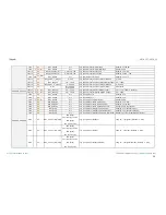
Page 25: ...C T DPT_UpDown 0 1 Ix Short Press Move Up Down Shutter Switching 0 1 Up Down 1 Bit C T DPT_Step 0 1 Ix Short Press Stop Step Up Shutter Sending of 0 Stop Step Up 1 Bit C T DPT_Step 0 1 Ix Short Press...

Page 26: ...rt Press Dimming Status Input 0 100 284 290 296 302 1 Bit C T DPT_Switch 0 1 Ix Long Press 0 Sending of 0 1 Bit C T DPT_Switch 0 1 Ix Long Press 1 Sending of 1 1 Bit I C T W DPT_Switch 0 1 Ix Long Pre...

Page 27: ...1 Bit O C T R DPT_Alarm 0 1 Ix Open Circuit Error 0 No Error 1 Open Circuit Error 309 338 367 396 1 Bit O C T R DPT_Alarm 0 1 Ix Short Circuit Error 0 No Error 1 Short Circuit Error 310 339 368 397 1...

Page 28: ...dby Economy Building Protection 328 357 386 415 1 Bit O C T R DPT_Switch 0 1 Ix C2 Detection State Binary Binary Value 329 358 387 416 1 Bit I C W DPT_Switch 0 1 Ix C2 Enable Channel According to para...

Page 29: ...n and send us your inquiries about Zennio devices http support zennio com Zennio Avance y Tecnolog a S L C R o Jarama 132 Nave P 8 11 45007 Toledo Spain Tel 34 925 232 002 www zennio com info zennio c...

Reviews: