background image

(Continued from previous page)

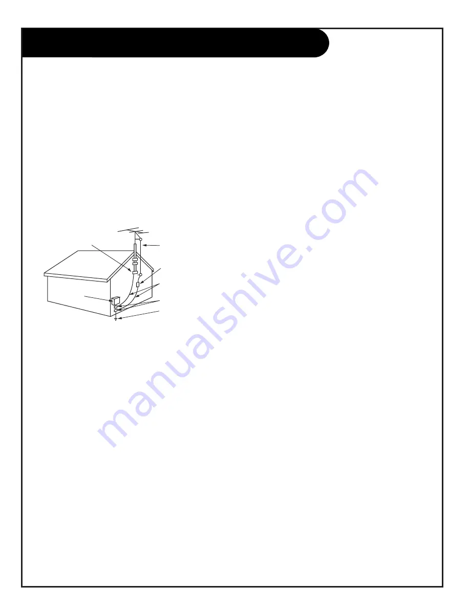
14. Outdoor Antenna Grounding

If an outside antenna or cable system is connected to the
product, be sure the antenna or cable system is grounded
so as to provide some protection against voltage surges
and built-up static charges. Article 810 of the National
Electrical Code (U.S.A.), ANSI/ NFPA 70 provides informa-
tion with regard to proper grounding of the mast and sup-
porting structure, grounding of the lead-in wire to an
antenna discharge unit, size of grounding conductors, loca-
tion of antenna-discharge unit, connection to grounding
electrodes, and requirements for the grounding electrode.

15. Lightning

For added protection for this product (receiver) during a
lightning storm, or when it is left unattended and unused
for long periods of time, unplug it from the wall outlet and
disconnect the antenna or cable system. This will prevent
damage to the product due to lightning and power-line
surges.

16. Power Lines

An outside antenna system should not be located in the
vicinity of overhead power lines or other electric light or
power circuits, or where it can fall into such power lines or
circuits. When installing an outside antenna system,
extreme care should be taken to keep from touching such
power lines or circuits as contact with them might be
fatal.

17. Overloading

Do not overload wall outlets and extension cords as this
can result in a risk of fire or electric shock.

18. Object and Liquid Entry

Never push objects of any kind into this product through

openings as they may touch dangerous voltage points or
short-out parts that could result in a fire or electric shock.
Never spill liquid of any kind on the product.

19. Servicing

Do not attempt to service this product yourself as opening
or removing covers may expose you to dangerous voltage
or other hazards. Refer all servicing to qualified service
personnel.

20. Damage Requiring Service

Unplug this product from the wall outlet and refer servic-
ing to qualified service personnel under the following con-
ditions:

a. If the power-supply cord or plug is damaged.

b. If liquid has been spilled, or objects have fallen into

the product.

c. If the product has been exposed to rain or water.

d. If the product does not operate normally by following

the operating instructions. Adjust only those controls that
are covered by the operating instructions as an improper
adjustment of other controls may result in damage and will
often require extensive work by a qualified technician to
restore the product to its normal operation.

e. If the product has been dropped or the cabinet has

been damaged.

f. If the product exhibits a distinct change in perfor-

mance.

21. Replacement Parts

When replacement parts are required, be sure the service
technician has used replacement parts specified by the
manufacturer or have the same characteristics as the origi-
nal part. Unauthorized substitutions may result in fire,
electric shock, or other hazards.

22. Safety Check

Upon completion of any service or repairs to this product,
ask the service technician to perform safety checks to
determine that the product is in proper operating condi-
tion.

23. Wall or Ceiling Mounting

The product should be mounted to a wall or ceiling only as
recommended by the manufacturer. The product may slide
or fall, causing serious injury to a child or adult, and seri-
ous damage to the product.

24. Heat

The product should be situated away from heat sources
such as radiators, heat registers, stoves, or other products
(including amplifiers) that produce heat.

Antenna Lead in Wire

Antenna Discharge Unit
(NEC Section 810-20)

Grounding Conductor
(NEC Section 810-21)

Ground Clamps

Power Service Grounding
Electrode System (NEC
Art 250, Part H)

Ground Clamp

Electric Service

Equipment

Example of Grounding According to National Electrical
Code Instructions

NEC - National Electrical Code

IMPORTANT SAFETY INSTRUCTIONS

206-3597-O

P A G E   4

Summary of Contents for IQC50H94W

Page 1: ...enith Electronics Corporation machine numbers IQC60H95W IQC50H95W IQC60H94W IQC50H94W o p e r a t i n g g u i d e w a r r a n t y t a b l e o f c o n t e n t s y o u r o n s c r e e n m e n u s p a g...

Page 2: ...es guidelines for proper grounding and in particular specifies that the cable ground shall be connected to the grounding system of the building as close to the point of the cable entry as practical RE...

Page 3: ...the manufac turer s instructions and should use a mounting accessory recommended by the manufacturer 8 Transporting Product A product and cart combination should be moved with care Quick stops excessi...

Page 4: ...d service personnel 20 Damage Requiring Service Unplug this product from the wall outlet and refer servic ing to qualified service personnel under the following con ditions a If the power supply cord...

Page 5: ...e and perform channel search Remote Button Functions 17 On Screen Displays 18 Front Panel Controls 19 On Screen Menus Overview 20 Step 3 Customize your TV s Features Setup Menu Language 22 Channel Add...

Page 6: ...layer S VHS VCR or High Definition Set Top Box go to page 12 To hook up your Entertainment Machine to an external stereo go to page 13 For Monitor Out Hookups go to page 14 Hookup Directory IMPORTANT...

Page 7: ...ect either an external amplifier or add a sub woofer to your surround sound system RF Connectors Antenna Cable 1 Antenna Cable 2 and Cable Box Used to connect cable service to the televi sion either d...

Page 8: ...Coaxial Wire 75ohm Locate the Antenna Cable 1 jack on the back of your Entertainment Machine Connect the cable that runs from the wall directly to this jack Turn to page 15 to continue setting up your...

Page 9: ...Turn to page 15 to continue setting up your Entertainment Machine Some cable services require the use of a cable box to decode premium channels and pay per view Using the To Cable Box to Decoder optio...

Page 10: ...he RF or VHF UHF CATV Out jack on the back of your VCR directly to this jack Find the composite video and audio jacks on the back of your VCR and connect them following the instructions provided with...

Page 11: ...jack to the Input jack on the back of your cable box Locate the Output jack on the back of your cable box Connect this to the Antenna Cable 2 jack on the back of your TV To view the premium stations...

Page 12: ...Set Top Box For several pieces of equipment edit the names under Source ID so you don t forget which is which See page 29 Some high end DVD players and High Definition Set Top Boxes use a pic ture re...

Page 13: ...DEO VIDEO 1 VIDEO 2 VIDEO AUDIO AUDIO AUDIO TO CABLE BOX Locate the Variable Out jacks on the back of your Entertainment Machine and the Input jacks on the back of your stereo s amplifier Connect the...

Page 14: ...r VCR to the Monitor Out jacks on the back of your Entertainment Machine as shown in the diagram to the right You may connect either the composite video or the S video cables to your Entertainment Mac...

Page 15: ...two AAA batter ies Make sure batteries are properly installed check the signs Turn on your Entertainment Machine by pressing the POWER button on your remote Press the MENU button on your remote Selec...

Page 16: ...50 COMPLETE Video Setup Special Audio Theater Video Setup Special Audio Theater Video Setup Special Audio Theater Quit To Exit To Menu Bar Menu Quit To Exit To Menu Bar Menu Quit To Exit To Menu Bar M...

Page 17: ...ARROW BUTTONS Allows you to move through on screen menu choices When Menus inactive arrow buttons activate Favorite Channels feature Must set Favorite Channels first Remote Control Part Number MBR 34...

Page 18: ...s active SECURITY TIMER Displays time that TV is set to turn off SLEEP TIMER SET Displays time left on Sleep Timer before TV shut off MAIN PICTURE SOURCE Displays Main Picture Source Active source hig...

Page 19: ...utton on the front panel and holding down on the button To turn Auto Demo off press the POWER button once 4 5 1 2 3 5 S Video Video L Mono R There are four jacks on the front of your Entertainment Mac...

Page 20: ...m for your DVD player or High Definition Set Top Box SPECIAL MENU Go beyond basics and customize your Entertainment Machine s functions Channel Labels 28 Label your channels with their network names A...

Page 21: ...sh Video Filter Color Temperature Aspect Ratio and V Position AU D I O M E N U 36 Customize the sound to suit your room and your taste Your options are Bass Treble Balance Reset and Advanced Settings...

Page 22: ...xit To Menu Bar Menu Quit To Exit To Menu Bar Menu Quit To Exit To Menu Bar Menu P A G E 2 2 Language Menu Choose the language you want the on screen menus to appear in power tv vcr cable aux source f...

Page 23: ...nel Review Nest Channel Clock Set Ch Ch Digital Setup Or Keys Component Input Press the Menu button on your remote to access the Setup menu Use the UP DOWN arrow to select Channel Add Del Press the RI...

Page 24: ...REVIEW ANT A CH I D SCAN LOCK 1 ON ON 2 3 4 5 6 7 8 Language Signal Auto Program Channel Add Del Channel Review Clock Set Digital Setup Component Input Video Setup Special Audio Theater Calendr Video...

Page 25: ...ons Press QUIT to save and exit Setup TO SET TIME 12 00 AM JAN 01 1999 Video Setup Special Audio Theater Language Signal Auto Program Channel Add Del Channel Review Clock Set Digital Setup Component I...

Page 26: ...izontal and vertical lines at one location on the screen Simply use the remote control to adjust the red and blue colors to match the green When properly aligned the outputs of all three tubes should...

Page 27: ...ou have an HD ready Set Top Box or a DVD player connected to your component video jacks Use SELECT to pick your choice Press QUIT to save and exit 6 206 3597 A NOTES To access this menu you must be tu...

Page 28: ...four and then press the SELECT button on your remote You will asked Are You Sure press SELECT again if you are sure Use CHANNEL UP DOWN buttons or the NUMBER KEYPAD and choose another channel to labe...

Page 29: ...e ID select Delete from step 5 then press the SELECT button You will be asked Are You Sure press QUIT to save and exit VID 1 VID 2 FRT VID Source List Custom Reset VCR 1 CD DVD TAPE LD AUX Video Setup...

Page 30: ...button on your remote and after a short time you will see three PIP insets representing three of the six Favorite channels you have selected for that category to the right of your viewing area Quit To...

Page 31: ...to reset to factory preset code Use the UP DOWN arrow buttons to select the Signal block press SELECT to confirm your choice Channel Selects the channel you wish to restrict This option only works if...

Page 32: ...ss the LEFT arrow button repeatedly until the cursor appears to the left of the current line item Use the DOWN arrow button to select Day Press LEFT RIGHT button to select which day of the week if nec...

Page 33: ...Closed Captions or Text shall be set to Usually this should be set to 1 Use the RIGHT arrow to select Press QUIT to save and exit Quit To Exit To Menu Bar Menu Quit To Exit To Menu Bar Menu Channel La...

Page 34: ...rce I D Favorite Channels Parental Control Security Timer Caption Text Background Gray Shaded Video Setup Special Audio Theater Video Setup Special Audio Theater Channel Labels Source I D Favorite Cha...

Page 35: ...esh Automatically monitors and adjusts the color to maintain con stant color levels even after a program or channel changes Video Filter Automatically reduces conspicuous noise in the picture without...

Page 36: ...only speakers from a separate stereo system Auto Noise Cancel Use to eliminate the noise between stations Loudness This function will improve the quality of both low and high frequency sounds when li...

Page 37: ...arrow but tons to select the Theater Modes Use the UP DOWN arrow buttons to choose which mode you prefer Each is a preset Audio Video configuration which enhances your viewing pleasure Use the UP DOW...

Page 38: ...accessible through the menus that pop up on screen when you use your remote There s more about that on the following page Just like your Entertainment Machine s main screen PIP will need a source to...

Page 39: ...s are tuned for the main screen PIP Inset Display channel tuning Channels are tuned for the PIP inset Note Available for Antenna 1 2 sources Press the SOURCE button on your remote when PIP display is...

Page 40: ...E With PIP displayed press the FREEZ button on your remote to freeze the PIP display Pressing FREEZ with PIP off will automatically bring up a PIP dis play with the Main Picture screen frozen at that...

Page 41: ...es Press and release the mode button VCR Cable Aux for the device you wish to program This will switch the remote to that mode Press and hold the mode button for the device you want to program until t...

Page 42: ...46 Sharp 19 Shintom 30 Shogun 45 Shinger 30 Sony 07 09 21 22 STS 02 Sylvania 00 15 22 29 31 Symphonic 00 Tatung 01 Teac 00 01 Technics 22 39 Teknika 00 22 23 Telefunken 43 TMK 27 45 Toshiba 15 16 20...

Page 43: ...Philips 12 Pioneer 17 27 Proton 12 QED 12 Quasar 13 RCA 11 31 Realistic 11 Rotel 12 SAE 12 Sansui 12 Scott 11 Sony 15 28 Technics 13 29 30 Victor 23 Aiwa 42 43 Hitachi 32 33 34 35 Jerrold 44 45 JVC 36...

Page 44: ...VCR Digit 7 Cbl Sat Stb Digit 7 Aux Digit 7 8 TV Digit 8 VCR Digit 8 Cbl Sat Stb Digit 8 Aux Digit 8 9 TV Digit 9 VCR Digit 9 Cbl Sat Stb Digit 9 Aux Digit 9 0 TV Digit 0 VCR Digit 0 Cbl Sat Stb Digit...

Page 45: ...ANING EXTENDED ABSENCE CABINET CLEANING WOOD CABINETS Even though you may be getting cable the signal may be weak which means the quality of your picture may suffer due to other factors If there are p...

Page 46: ...u If your audio mode is set to SAP that channel may not have a SAP program No picture and unclear sound Press source on your remote make sure you have selected the right source you want to watch Are y...

Page 47: ...sound Check to see if the source equipment has been turned on Make sure that the connections are when any non cable source secure on the back of your Entertainment Machine and on the source equipment...

Page 48: ...DVD or other A V device ANTENNA The physical receiver of television signals sent over the air CAPTIONS A form of subtitling that writes out the dialog for your program CONVERGENCE This option lets yo...

Page 49: ...le or on the air to your television screen SOURCE The term for the equipment that provides audio and video information to your Entertainment Machine Antenna VCR DVD players or Cable Boxes are examples...

Page 50: ...206 3597 A P A G E 4 8 Notes...

Page 51: ...LESS STEREO HEADPHONES Use Your Visa or MasterCard to Order PLEASE ALLOW 3 4 WEEKS FOR DELIVERY zenith ORDER TODAY CALL OR FAX TOLL FREE 1 800 255 6790 Fax 1 888 693 6484 email parts sales zenith com...

Page 52: ...e Read your Operating Guide carefully so that you will understand the operation of your set and how to adjust the customer controls Carry In Service Models under 21 diagonal U S A screen size must be...

Reviews: