background image

(Continued from previous page)

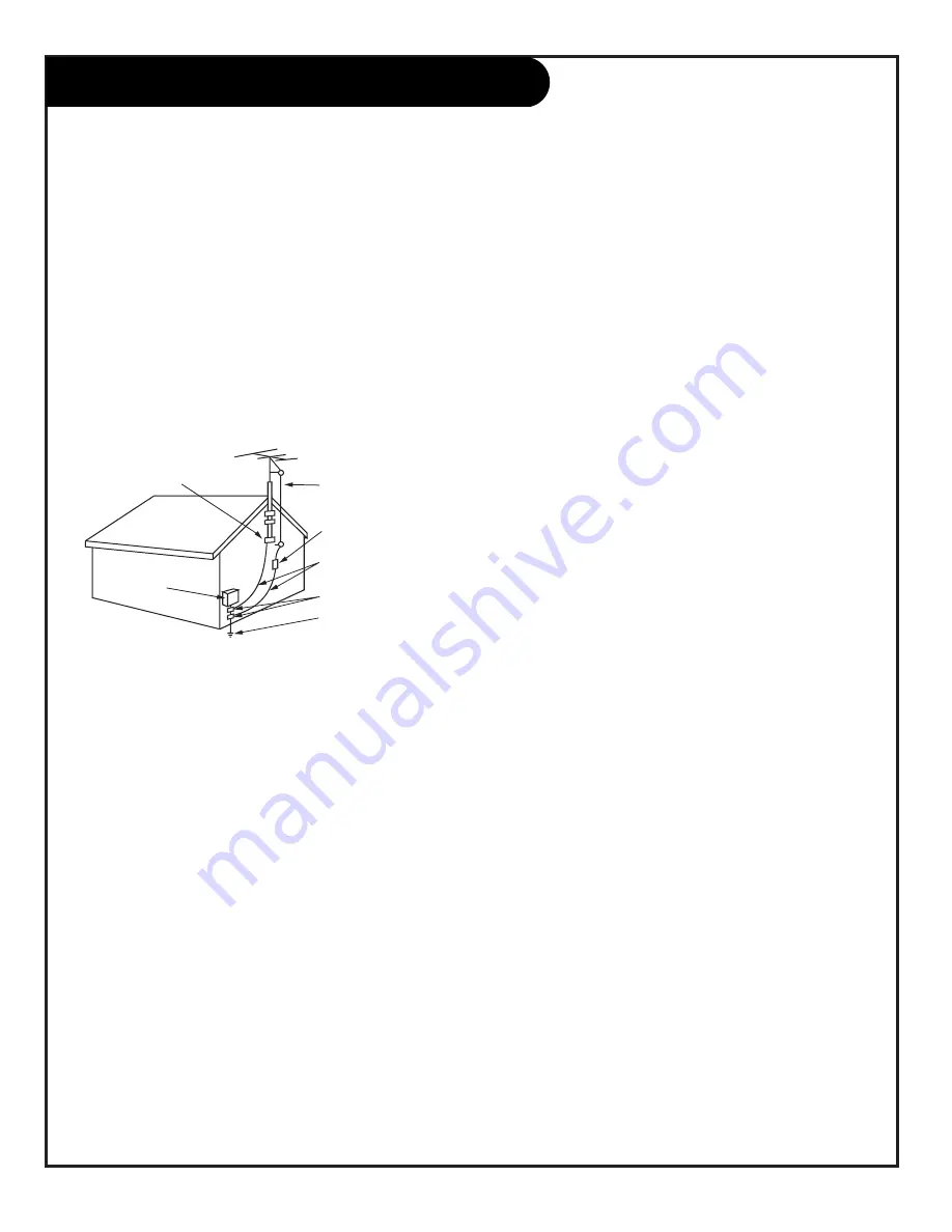
14. Outdoor Antenna Grounding

If an outside antenna or cable system is connected to the
product, be sure the antenna or cable system is grounded
so as to provide some protection against voltage surges
and built-up static charges. Article 810 of the National
Electrical Code (U.S.A.), ANSI/ NFPA 70 provides informa-
tion with regard to proper grounding of the mast and sup-
porting structure, grounding of the lead-in wire to an
antenna discharge unit, size of grounding conductors, loca-
tion of antenna-discharge unit, connection to grounding
electrodes, and requirements for the grounding electrode.

15. Lightning

For added protection for this product (receiver) during a
lightning storm, or when it is left unattended and unused
for long periods of time, unplug it from the wall outlet and
disconnect the antenna or cable system. This will prevent
damage to the product due to lightning and power-line
surges.

16. Power Lines

An outside antenna system should not be located in the
vicinity of overhead power lines or other electric light or
power circuits, or where it can fall into such power lines or
circuits. When installing an outside antenna system,
extreme care should be taken to keep from touching such
power lines or circuits as contact with them might be
fatal.

17. Overloading

Do not overload wall outlets and extension cords as this
can result in a risk of fire or electric shock.

18. Object and Liquid Entry

Never push objects of any kind into this product through

openings as they may touch dangerous voltage points or
short-out parts that could result in a fire or electric shock.
Never spill liquid of any kind on the product.

19. Servicing

Do not attempt to service this product yourself as opening
or removing covers may expose you to dangerous voltage
or other hazards. Refer all servicing to qualified service
personnel.

20. Damage Requiring Service

Unplug this product from the wall outlet and refer servic-
ing to qualified service personnel under the following con-
ditions:

a. If the power-supply cord or plug is damaged.

b. If liquid has been spilled, or objects have fallen into

the product.

c. If the product has been exposed to rain or water.

d. If the product does not operate normally by following

the operating instructions. Adjust only those controls that
are covered by the operating instructions as an improper
adjustment of other controls may result in damage and will
often require extensive work by a qualified technician to
restore the product to its normal operation.

e. If the product has been dropped or the cabinet has

been damaged.

f. If the product exhibits a distinct change in perfor-

mance.

21. Replacement Parts

When replacement parts are required, be sure the service
technician has used replacement parts specified by the
manufacturer or have the same characteristics as the origi-
nal part. Unauthorized substitutions may result in fire,
electric shock, or other hazards.

22. Safety Check

Upon completion of any service or repairs to this product,
ask the service technician to perform safety checks to
determine that the product is in proper operating condi-
tion.

23. Wall or Ceiling Mounting

The product should be mounted to a wall or ceiling only as
recommended by the manufacturer. The product may slide
or fall, causing serious injury to a child or adult, and seri-
ous damage to the product.

24. Heat

The product should be situated away from heat sources
such as radiators, heat registers, stoves, or other products
(including amplifiers) that produce heat.

P A G E   4

3-WireRev6/00

IMPORTANT SAFETY INSTRUCTIONS

Antenna Lead in Wire

Antenna Discharge Unit
(NEC Section 810-20)

Grounding Conductor
(NEC Section 810-21)

Ground Clamps

Power Service Grounding
Electrode System (NEC
Art 250, Part H)

Ground Clamp

Electric Service

Equipment

Example of Grounding According to National Electrical
Code Instructions

NEC - National Electrical Code

Summary of Contents for D56W25

Page 1: ...Copyright 2001 Zenith Electronics Corporation Operating Guide Warranty Machine Numbers D56W25 D61W25 D65W25 Projection TVs t a b l e o f c o n t e n t s p a g e 5...

Page 2: ...with the limits for a Class B digital device pursuant to Part 15 of the FCC Rules These limits are designed to provide reasonable protection against harmful interference when the equipment is operated...

Page 3: ...Any mounting of the product should follow the manufac turer s instructions and should use a mounting accessory recommended by the manufacturer 8 Transporting Product A product and cart combination sho...

Page 4: ...service personnel 20 Damage Requiring Service Unplug this product from the wall outlet and refer servic ing to qualified service personnel under the following con ditions a If the power supply cord or...

Page 5: ...Picture 41 Split Screen 2 Channel Viewing 42 Remote Control Programming 43 47 Maintenance 48 Troubleshooting 49 51 Glossary 52 Notes 53 54 Recommended Accessories 55 Warranty Back Cover Note Design a...

Page 6: ...or standard video input TIPS ON REAR PANEL CONNECTIONS S VIDEO connections are provided for high performance laserdisc players VCRs etc that have this feature Use these connections in place of the sta...

Page 7: ...ectors Antenna Cable 1 Antenna Cable 2 and Cable Box Used to connect cable service to the televi sion either directly or through your cable box Right Left Audio Used for stereo sound from various type...

Page 8: ...small device that connects a two wire 300 ohm antenna to a 75 ohm RF jack They are usually about an inch long with two screws on one end and a round opening with a wire sticking out on the other end...

Page 9: ...to page 15 to continue setting up your Entertainment Machine Some cable services require the use of a cable box to decode premium channels and pay per view Using the To Cable Box to Decoder option an...

Page 10: ...e coming from the RF or VHF UHF CATV Out jack on the back of your VCR directly to this jack Find the composite video and audio jacks on the back of your VCR and connect them follow ing the instruction...

Page 11: ...the back of your cable box Locate the Output jack on the back of your cable box Connect this to the Antenna Cable 2 jack on the back of your TV To view the premium stations set the channel number on y...

Page 12: ...Box For several pieces of equipment edit the names under Source ID so you don t forget which is which See page 31 Some high end DVD players and High Definition Set Top Boxes use a pic ture reproductio...

Page 13: ...Audio Menu See page 39 Send the sound from your Entertainment Machine to an external audio amplifier system use it to hear the audio External stereo amplifier Audio cables not included with TV VARIABL...

Page 14: ...VCR Connect the Input jacks from your VCR to the Monitor Out jacks on the back of your Entertainment Machine as shown in the diagram You may connect either the composite video or the S video cables to...

Page 15: ...onfirm your choice then press the MENU button to return to the Setup Menu Continue to the next page to scan for available channels Trilingual Menus Signal Antenna Scan CATV 1 Channel Add Del CATV 2 Ch...

Page 16: ...ocus Picture Formats Installing Channel 110 50 Complete Quit To Exit To Menu Bar Menu Quit To Exit To Menu Bar Menu Quit To Exit To Menu Bar Menu Trilingual Menus Signal Scan Begin Channel Add Del Cha...

Page 17: ...t chapter scan for DVD SKIP I Right chapter scan for DVD NUMBER KEYPAD 0 9 Selects channels directly and enters numerical values Digital Mode Dash Use as the dash when selecting digital channel number...

Page 18: ...me that TV is set to turn off SLEEP TIMER SET Displays time left on Sleep Timer before TV shut off MAIN PICTURE SOURCE Displays Main Picture Source Active source highlighted MONTH DATE YEAR Shows curr...

Page 19: ...other menu options using the above proce dure or if you are done changing the menu option settings Press QUIT to remove the menus from the TV screen On Screen Menu Operation 1 2 3 4 Additional instru...

Page 20: ...INPUT 2 S VIDEO S VIDEO MONO L R MONO L R VIDEO VIDEO AUDIO AUDIO INPUT 3 INPUT 4 Y VIDEO PB PR R MONO L AUDIO Y VIDEO PB PR R MONO L AUDIO MONITOR OUT S VIDEO L R VIDEO AUDIO Input 5 Video Audio S V...

Page 21: ...they do on your remote control Auto Demo is activated by pressing the POWER button on the front panel and holding down on the button To turn Auto Demo off press the POWER button once There are four ja...

Page 22: ...ock on your Entertainment Machine HD Focus 28 Use to have the TV automatically adjust the color convergence Picture Formats 29 Choose the picture aspect style for your DVD player or High Definition Se...

Page 23: ...our options are Bass Treble Balance Reset and Advanced Settings Stereo Mono Second Audio Program Internal Speakers Auto Noise Cancel Loudness and SoundRite T H E AT E R M E N U 40 Select the right aud...

Page 24: ...L Press select to set SETUP SEL Press select to set SETUP Choose the language you want the on screen menus to appear in English French or Spanish Press MENU to access the Setup menu Use the DOWN arrow...

Page 25: ...Set Ch Ch HD Focus Or Keys Picture Formats VIDEO SETUP AUDIO THEATER SEL SPECIAL SEL Press select to set SETUP SEL Press select to set SETUP Press the MENU button on your remote to access the Setup me...

Page 26: ...ur Entertainment Machine Quit To Exit To Menu Bar Menu CHANNEL REVIEW Ant 1 Ch Id Scan Lock 1 ON ON 2 3 4 5 6 7 8 Trilingual Menus Signal Scan Channel Add Del Channel Review Clock Set HD Focus Picture...

Page 27: ...choose Clock Set Use the RIGHT arrow button to set the clock on your Entertainment Machine Use the RIGHT arrow button to choose first the time option and use the UP DOWN arrow but tons to adjust time...

Page 28: ...access the Setup menu Use the UP DOWN arrow to choose HD Focus Press the RIGHT arrow button to go to the HD Focus option Press Select to adjust color convergence auto matically Let your Entertainment...

Page 29: ...e and set the options based on your equipment s signal requirements for high definition or standard NTSC sources Aspect Style Normal Wide Zoom Panorama V Position Image vertical position on screen Com...

Page 30: ...a channel choose Reset using the UP DOWN arrow buttons from Step 5 and then press the SELECT button on your remote You will asked Are You Sure press SELECT again if you are sure Use CHANNEL UP DOWN b...

Page 31: ...abel or pick Reset to clear all labels If you chose Source List press the RIGHT arrow button to access the list and then use the UP DOWN arrow buttons to pick an ID from the list Press SELECT to save...

Page 32: ...e Channels Mode press the MENU but ton on your remote and after a short time you will see three channel Pop 3 still frame insets representing three of the six Favorite channels you have selected for t...

Page 33: ...on t forget the password it is the only way you can access the Parental Control menu and change rating selections or turn Parental Control off TV PARENTAL GUIDELINE RATING SYSTEM TV G General Audience...

Page 34: ...Canadian broadcasting Eng Canadian Ratings Fra Sets age ratings for Canadian broadcasting Fra For each rating menu use the UP DOWN arrow buttons to choose the level of rating you wish to block Press t...

Page 35: ...cessary Press the LEFT arrow button repeatedly until the cursor appears to the left of the current line item Use the DOWN arrow to choose Channel Set the channel for the TV to tune to by entering the...

Page 36: ...s not appear Auto Caption text option appears when sound is muted Press the DOWN arrow button to choose the mode C C for Closed Captions or Text for Text Use the RIGHT arrow button to choose and press...

Page 37: ...ow button to access the Special Menu Use the UP DOWN arrow to choose Background Press the RIGHT arrow button to activate the Background option Use the UP DOWN arrow to choose Solid or Shaded Solid Pic...

Page 38: ...ow button to activate the Advanced Settings menu Use the UP DOWN arrow to choose from the following options Press SELECT to confirm your choice Light Sentry Automatically monitors and adjusts contrast...

Page 39: ...options Press SELECT to confirm your choice Stereo Activate stereo sound Mono Activate mono sound Second Audio Programming Activates separate audio channel avail able with some programming Internal Sp...

Page 40: ...e you prefer Each is a preset setup designed to enhance your viewing experience Use the UP DOWN arrow to choose Reset Reset restores the levels to their original settings Press SELECT to confirm your...

Page 41: ...ulti channel display also includes the channel number for reference POP 3 will continue to dis play all the channels continuously three channels at a time Press MULTI again to turn POP 3 off 1 2 3 4 5...

Page 42: ...nel tuning to the additional channel Tune to a channel for the additional channel picture Press PIP CH to switch channel tuning back to the original channel Press SPLIT again to turn the feature off a...

Page 43: ...until the indicator light turns on continue holding down the mode key Using the NUMBER keypad enter the three number Brand Code found in the chart on the Brand Code reference pages following two page...

Page 44: ...266 282 725 Quasar 259 295 Radio Shack 213 265 730 RCA 216 220 228 240 242 249 260 266 282 283 284 285 286 287 288 708 710 711 725 Realistic 212 213 265 730 Saisho 722 Salora 297 Samsung 220 230 Sans...

Page 45: ...itsubishi 927 Nakamichi 925 926 Onkyo 923 924 946 Optimus 920 921 922 Panasonic 431 432 945 Phillips 421 433 434 Pioneer 431 435 944 Quasar 432 Radio Shack 431 441 RCA 437 943 Sanyo 438 439 Sears 936...

Page 46: ...t 5 HD STB Digit 5 6 TV Digit 6 VCR Digit 6 Cable Digit 6 DVD Digit 6 HD STB Digit 6 7 TV Digit 7 VCR Digit 7 Cable Digit 7 DVD Digit 7 HD STB Digit 7 8 TV Digit 8 VCR Digit 8 Cable Digit 8 DVD Digit...

Page 47: ...CR Enter Cable Sat Enter DVD Enter HD STB Enter menu TV Menu VCR Menu Cable Sat Menu DVD Menu HD STB Menu Disc Menu theater TV Theater Modes N A Cable Sat Info DVD Open Close HD STB Info record VCR Re...

Page 48: ...et the cabinet air dry before turning the TV on Use a quality wood cleaner and polish This will protect the TV from dirt and dust as well as keep the cabinet looking new If you leave your TV dormant O...

Page 49: ...Notify cable company of reception problem Picture wobbles or drifts CATV wire not connected or loose Make or tighten connection 6 12 Local interference Try different channel Turn off interfering appl...

Page 50: ...u Aspect Ratio Use correct aspect ratio for source s image 16x9 or 4x3 29 Snowy or Poor Picture Wrong Ant connection location Move antenna check connection location Check cable input TV VCR button set...

Page 51: ...pment on Tape or Disk not playing Press PLAY on source equipment Try another channel The problem may be with the broadcast not your TV 17 21 Wires incorrectly connected Install wires correctly on TV a...

Page 52: ...her A V equipment ANTENNA The physical receiver of television signals sent over the air A large metal piece of equipment does not always have to be visible for your home to be using an antenna DELETED...

Page 53: ...P A G E 5 3 206 3594 Notes...

Page 54: ...P A G E 5 4 206 3594 Notes...

Page 55: ...up ONLY 34 95 PLUS 6 95 SHIPPING HANDLING INDOOR AMPLIFIED ANTENNA ATS 775 ORDER TODAY CALL OR FAX TOLL FREE 1 800 255 6790 Fax 1 888 693 6484 email parts sales zenith com Watch your favorite show wit...

Page 56: ...controls calibration maintenance or failure to maintain or separate system components To damages or operating problems that result from normal wear and tear misuse abuse operation outside envi ronment...

Reviews: