2
HDVI5 Component Video Switch
3
HDVI5 Component Video Switch
DIGITAL VIDEO
1 2 3 4 5
IR / Z-IN Z-OUT
RS232
1 2 3
4 5 OUT
DIGITAL
AUDIO
1 2 3 4 5 OUT
AUX1 AUX2
9VDC
N/O COM COM N/C N/O COM COM N/C
1
2
3
4
5
6
7
8
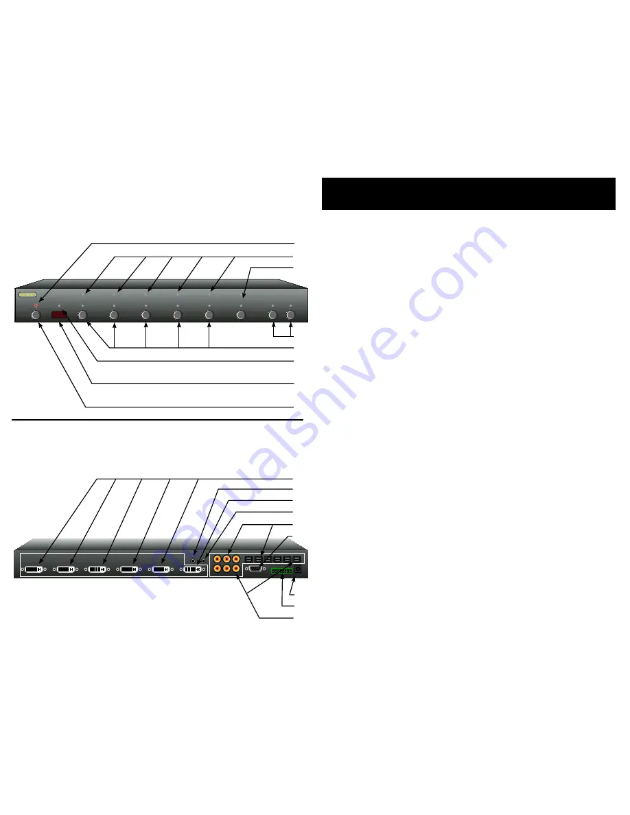
Front Panel Controls:
Power Indicator. Lights up in standby mode.
Selection LEDs. Indicate currently selected inputs.
Select between Normal/Audio/Video Break away.
Toggle Auxiliar y Relays.
Input Selection Buttons.
Infrared Received Indicator. Flashes when IR is received.
Infrared Remote Sensor Window.
Power Toggle Button.
Rear Panel Connections:
DVI Inputs. DVI, or HDMI when using conversion cable,
compatible digital inputs. All inputs are fully HDCP compat-
ible with both DVI and HDMI formats. All inputs are fully
HDMI audio compatible.
IR Input or +2V Trigger Input. Accepts modulated or un-
modulated IR signals, or +2V Trigger On/O ff voltage.
DVI Output (or HDMI Output when using conversion cable).
Z- OUT currently unused, reser ved for future use.
Digital Audio Inputs. Each video input has an associated
digital audio channel with both a Coax and an Optical con-
nection. Only one of the two types of inputs can be active
at any time. The HDVI5 will auto -select between the two
types of signals. If a signal is supplied to both the Coax and
Optical inputs, the Coax signal is given priority.
RS-232 Por t.
DC Power Jack Connector.
Auxiliar y Relay Connections.
Digital Audio Outputs. All digital audio inputs are automat-
ically conver ted to both Coax and Optical outputs. Both the
Coax and Optical outputs are available simultaneously.
1.
2.
3.
4.
5.
6.
7.
8.
1.
2.
3.
4.
5.
6.
7.
8.
9.
1 2 3 4 5 SEL A1 A2
Front Panel
Rear Panel
An Overview of the HDVI5
1
2
3
4
5
6
7
8
9


