background image


          11 / 136 

Identification: MD-AL-GI-00 
Rev. 1.1 of 15/03/2021 - Application: GID 

User’s Manual 3PH 20000TL - 33000TL-V2  
Rev. 1.1 15/03/2021 

Maintenance and repair 


Before carrying out any repairs, disconnect the inverter from the mains 

network (AC side) and from the photovoltaic system (DC side). 


After switching off the AC and DC switches, wait 5 minutes before carrying 
out any repairs or maintenance on the inverter! 
 

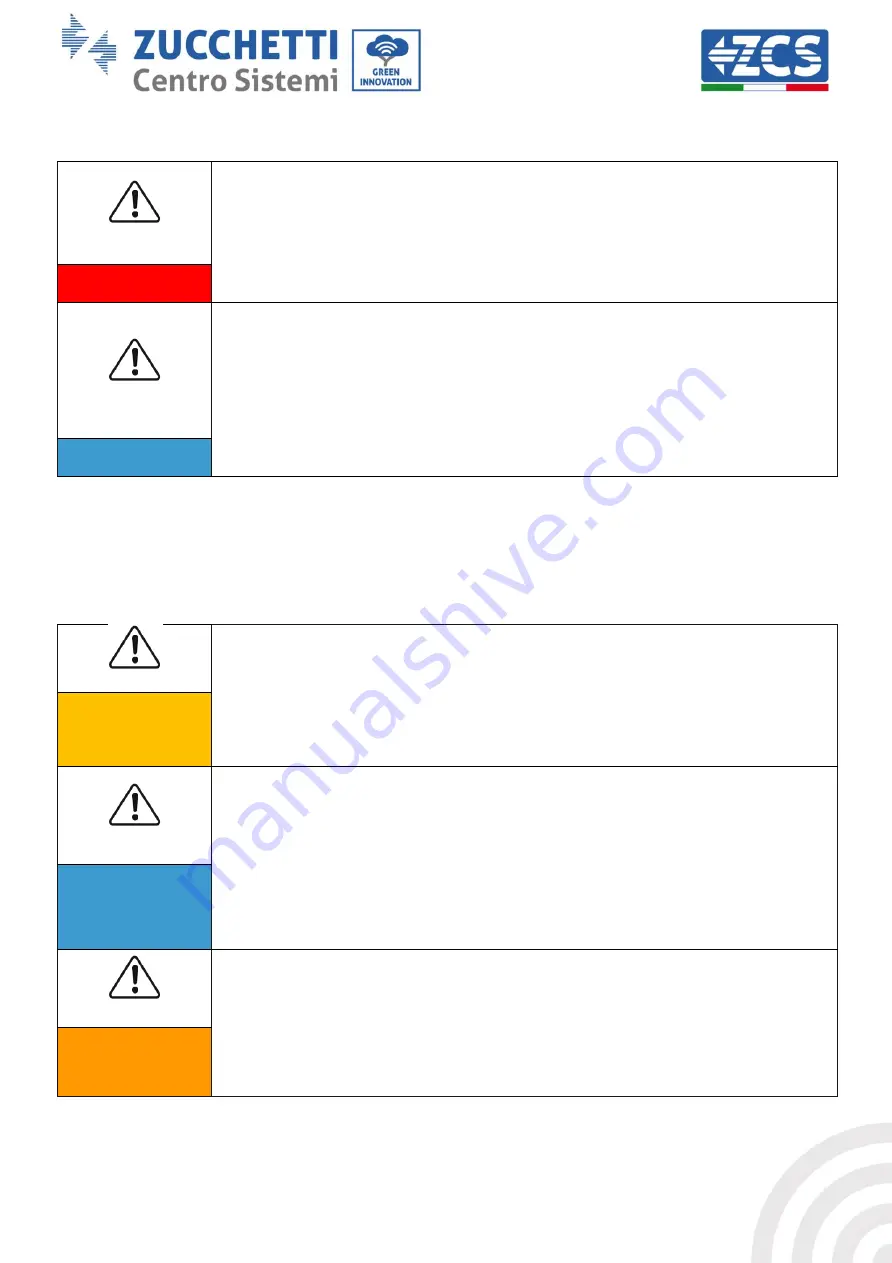
Danger 


The inverter should start working again after any faults have been fixed. For 
any repairs, contact your local authorised service centre; 


Do not disassemble the internal components of the inverter without 
permission. This will void the warranty. Zucchetti Centro Sistemi S.p.A. shall 
not be responsible for any damage or loss caused by these actions. 
 

Attention


1.2.


Symbols and icons 

Safety signals 


Pay attention to possible burns due to hot parts. 

Only touch the screen or press the keys while the inverter is in operation. 


Caution 


The  PV  strings  should  be  connected  to  the  ground  in  accordance  with  the 
local regulations! 

To ensure the safety of the system and people, the inverter and photovoltaic 
strings must be securely connected to the ground. 


Attention


Ensure  the  correct  DC  input  voltage;  which  must  be  below  the  maximum 
allowable  DC  voltage.  Overvoltage  can  cause  permanent  damage  to  the 
inverter or other faults which are not covered by the warranty! 


Warning


Summary of Contents for Azzurro 3PH 20000TL-V2

Page 1: ......

Page 2: ...uova Bracciolini Arezzo Italy tel 39 055 91971 fax 39 055 9197515 innovation zcscompany com zcs pec it www zcsazzurro com Reg Pile IT12110P00002965 Share Capital 100 000 00 fully paid up AR Company Reg no 03225010481 REA AR no 94189 ISO 9001 Certified Company Certificate no 9151 CNS0 IT 17778 Grid connected inverter 3PH 20000TL 33000TL V2 User Manual ...

Page 3: ...ess 24 3 2 Checks before installation 24 3 3 Installation tools 26 3 4 Installation position 28 3 5 Moving the 3PH 20000TL 33000TL V2 inverter 30 3 6 Installing the 3PH 20000TL 33000TL V2 inverter 31 4 Electrical connections 33 4 1 Electrical connections 34 4 2 Connecting PNGD cables grounding 34 4 3 Connecting the DC input power cables 36 4 4 Connecting the AC output power cables 42 4 5 Connectin...

Page 4: ...83 10 1 2 Configuration 84 10 1 3 Verification 93 10 1 4 Troubleshooting 97 10 2 Ethernet adapter 102 10 2 1 Installation 102 10 2 2 Verification 104 10 2 3 Troubleshooting 106 10 3 4G adapter 107 10 3 1 Installation 107 10 3 2 Verification 110 10 4 Datalogger 113 10 4 1 Preliminary notes on how to configure the datalogger 113 10 4 2 Electrical connections and configuration 114 10 4 3 ZSM DATALOG ...

Page 5: ...ble 128 10 4 7 4 Connecting the power supply and battery pack to the Datalogger 128 10 4 7 5 Connecting the LM2 485 PRO cell irradiance and temperature sensor to the datalogger 129 10 4 8 Configuring the Datalogger 130 10 4 8 1 Configuring the Datalogger on the ZCS Azzurro portal 133 10 4 8 2 Network configuration 134 10 4 9 Local monitoring 135 10 4 9 1 Requirements for installation of local moni...

Page 6: ...plant Copyright statement Copyright of this manual belongs to Zucchetti Centro Sistemi S p A No part of this manual including the software etc may be copied reproduced or distributed in any form or by any means without the permission of Zucchetti Centro Sistemi S p A All rights reserved ZCS reserves the right to final interpretation This manual is subject to change based on feedback from users ins...

Page 7: ...sonnel installers technicians electricians technical support personnel or anyone who is qualified and certified to operate a photovoltaic system who are responsible for installing and starting the inverter in the photovoltaic system and for operators of the photovoltaic system Symbols used This manual provides information for safe operation and uses certain symbols to ensure the safety of personne...

Page 8: ...hazardous situation which if not resolved or avoided could result in minor or moderate personal injury Caution Attention indicates a potentially hazardous situation which if not resolved or avoided could result in damage to the system or other property Attention Note provides important tips on the correct and optimal operation of the product Note ...

Page 9: ...onnections are carried out by a qualified electrician Contact the nearest authorised service centre for any repairs or maintenance Contact your distributor for information on the nearest authorised service centre DO NOT carry out repairs yourself as this may result in injury or damage Before installing and operating the equipment the electrical circuit of the strings must be disconnected by openin...

Page 10: ...re 1 Do not lose or damage this manual Transport requirements If you encounter problems with the packaging or if you find any visible damage please notify the transport company immediately If necessary request assistance from an installer of photovoltaic systems or from Zucchetti Centro Sistemi SpA Transport of the equipment especially by road must be carried out with vehicles suitable to protect ...

Page 11: ...operator and that all the electrical connections are made by a professional electrician Attention Do not remove the information label or open the inverter Otherwise ZCS will not provide any warranty or maintenance Note Operation Contact with the electrical grid or the terminal of the equipment may cause electrocution or fire Do not touch the terminal or the conductor connected to the electrical gr...

Page 12: ...ents of the inverter without permission This will void the warranty Zucchetti Centro Sistemi S p A shall not be responsible for any damage or loss caused by these actions Attention 1 2 Symbols and icons Safety signals Pay attention to possible burns due to hot parts Only touch the screen or press the keys while the inverter is in operation Caution The PV strings should be connected to the ground i...

Page 13: ...tage may be present on the inverter Before opening the inverter wait 5 minutes to ensure that the capacitors are completely discharged Beware of high voltage Beware of high temperatures Complies with the European Standards CE Ground connection point Read this manual before installing the inverter Indication of the allowable temperature range Degree of protection of the equipment according to the I...

Page 14: ... 20000TL 33000TL V2 inverters are grid connected photovoltaic inverters equipped with a dual channel MPPT capable of converting the direct current generated by the photovoltaic strings into three phase sine wave alternating current and feeding the energy to the public electricity grid An AC circuit breaker see related chapter must be used as a disconnecting device and must always be easily accessi...

Page 15: ...d networks The 3PH 20000TL 33000TL V2 TL inverters are compatible with network configurations TN S TN C TN C S TT IT For the type of TT electrical grid the voltage between neutral and ground must be less than 30V The figure below shows the diagrams of the grids just described Figure 3 Wiring diagrams of grid types on which the 3PH 20000TL 33000TL V2 inverter can be installed Inverter components In...

Page 16: ...RS485 cable entry 6 AC cable entry 7 Cooling fans 8 DC negative pole connectors The inverter model must be chosen by a qualified technician who knows the installation conditions the devices that will be installed outdoors and the possible integration with existing systems Optional components of the inverter should be chosen by a qualified technician who is familiar with the installation conditions...

Page 17: ...16 136 Identification MD AL GI 00 Rev 1 1 of 15 03 2021 Application GID User s Manual 3PH 20000TL 33000TL V2 Rev 1 1 15 03 2021 Figure 5 Front side and back view of the inverter and bracket ...

Page 18: ...unctioning properly At the same time the control board can activate the protection relay in order to protect the internal components Operating principles The DC switch disconnects the internal circuits from the DC input for maintenance purposes The control board of the strings measures the input current and voltage analyses the functioning state of each PV string and if anomalies are found on the ...

Page 19: ... s Manual 3PH 20000TL 33000TL V2 Rev 1 1 15 03 2021 The communication board allows the inverter to communicate via RS485 and Wi Fi optional the user can access all operating data via web portal from a PC and via APP Figure 7 Block diagram of the 3PH 20000TL 33000TL V2 inverters ...

Page 20: ...the amount of active power fed into the grid at the desired value expressed as a percentage To achieve this limitation it is necessary to use an external device Anti Reverse Power Controller not included with the inverter B 4 Automatic power reduction when grid is over frequency When the grid frequency exceeds the limit set the inverter reduces the power in order to ensure the stability of the gri...

Page 21: ...cessors it is sufficient for one of the two to detect a fault in order to trigger the protection resulting in separation from the grid and shutdown of the operation C Grid monitoring Continuous monitoring of the grid voltage to ensure that the voltage and frequency values stay within the operating limits D Internal protection of the inverter device The inverter has all kinds of internal protection...

Page 22: ...erating curves Efficiency curve for an Azzurro ZCS model belonging to the 3PH 20000TL 33000TL V2 family Figure 8 Efficiency curve for an Azzurro ZCS 3PH 20000TL 33000TL V2 inverter Input voltage derating curve for an Azzurro ZCS 3PH 20000TL 33000TL V2 inverter Figure 9 Input voltage derating curve for an Azzurro ZCS 3PH 20000TL 33000TL V2 inverter ...

Page 23: ... User s Manual 3PH 20000TL 33000TL V2 Rev 1 1 15 03 2021 Output voltage derating curve for an Azzurro ZCS model belonging to the 3PH 20000TL 33000TL V2 family Figure 10 Output voltage derating curve for an Azzurro ZCS inverter belonging to the 3PH 20000TL 33000TL V2 family ...

Page 24: ... of the inverter when handling and transporting the inverter Choose an appropriate mounting position and surface Assign at least two people to install the inverter Attention A Installation process This section describes the process for installing the 3PH 20000TL 33000TL V2 inverter B Checks before installation This section describes the checks to carry out on the outer packaging on the inverter an...

Page 25: ...ars If any kind of damage is found do not open the box containing the inverter and contact the supplier and transport company as soon as possible It is recommended to remove the packaged materials from the box 24 hours before installing the inverter Checking the product After removing the inverter from its packaging check that the product is intact and complete If any damage is found or components...

Page 26: ...W 6 Input terminals 25 33 kW 4 Input terminals 20kW 6 Input terminals 25 33 kW 4 metal terminals for DC power cables 20kW 6 metal terminals for DC power cables 25 33 kW 4 metal terminals for DC power cables 20kW 6 metal terminals for DC power cables 25 33 kW 2 M6 hexagonal screws 6 M8x80 screws and expansion plugs 1 Warranty Registration 1 user manual 2 warranty 1 Outgoing inspection report ...

Page 27: ...To drill holes in the wall for fixing the bracket 2 Screwdriver To screw and unscrew screws for the various connections 3 Wire stripper To prepare the cables for wiring 5 Adjustable spanner opening greater than 32 mm To tighten the bolts 6 4 mm Allen key 6 mm Allen key To screw the inverter to the wall mounting bracket and to open the front cover of the inverter 7 M5 socket wrench To tighten the b...

Page 28: ...nal pliers To cut and tighten the cable ends 12 Wire stripping tool To remove the outer sheath of the cables 13 RJ45 2 pieces 14 Cable cutter To cut the power cables 15 Crimping tool To crimp the power cables 16 Multi meter To check the voltage and current values 17 Marker pen To mark the wall for better fixing precision 18 Measuring tape To measure distances 19 Level To make sure the bracket is l...

Page 29: ...L 33000TL V2 Rev 1 1 15 03 2021 20 ESD gloves Protective clothing 21 Safety goggles Protective clothing 22 Protection mask Protective clothing 3 4 Installation position Choose an appropriate installation location for the inverter Follow the requirements below to determine the installation position ...

Page 30: ...on MD AL GI 00 Rev 1 1 of 15 03 2021 Application GID User s Manual 3PH 20000TL 33000TL V2 Rev 1 1 15 03 2021 Figure 12 Requirements or installing a single inverter Figure 13 Requirements for installing multiple inverters ...

Page 31: ...talled at higher heights must be moved to the ground before they can be repaired or serviced 3 5 Moving the 3PH 20000TL 33000TL V2 inverter This section describes how to move the inverter correctly 1 When opening the packaging insert your hands into the slots on both sides of the inverter and take a hold of it as shown in Figures below Two people are needed to carry out this operation in order to ...

Page 32: ...wall using a level to ensure that it is straight mark the 6 holes using a suitable marker pen Keeping the hammer drill perpendicular to the wall and avoiding any sudden movements when drilling drill the 6 holes at the points marked on the wall using a 8 mm drill bit In case of errors during drilling it is necessary to reposition the holes 2 Insert the plugs horizontally into the holes made paying ...

Page 33: ...32 136 Identification MD AL GI 00 Rev 1 1 of 15 03 2021 Application GID User s Manual 3PH 20000TL 33000TL V2 Rev 1 1 15 03 2021 Figure 16 Steps for mounting the inverter on the wall ...

Page 34: ...arge completely The inverter must be installed and serviced by professional technicians or electricians Attention The PV modules generate electricity when exposed to sunlight which can pose a risk of electric shock Before connecting the DC input power cord be sure to disconnect the strings via the appropriate circuit breakers Danger The maximum open circuit voltage of the photovoltaic string must ...

Page 35: ... for connecting the cables 4 2 Connecting PNGD cables grounding Connect the 3PH 20000TL 33000TL V2 inverter to the ground electrode using ground protection cables PGND The inverter does not have a transformer therefore the positive and negative polarities of the photovoltaic string do NOT need to be grounded Otherwise the inverter may fail All non current carrying metal parts such as the PV module...

Page 36: ...repare the PGND cables to be connected outdoor power cables with a cross section of 8 mm2 are recommended for grounding purposes it is recommended to use yellow green cables for better identification Procedure 1 Remove an adequate length of the external insulation layers using a wire stripper as shown in Figure below Remove an adequate length of the external insulation layers using a wire stripper...

Page 37: ... ensure the anti corrosion performances of the ground terminals apply silica gel on them after connecting the ground cable 4 3 Connecting the DC input power cables Connect the 20 33K TL inverter to the photovoltaic strings using DC input power cables Select the input mode the 20 33K TL inverter has two MPPTs which can function either independently or in parallel depending on how the system was des...

Page 38: ...be connected separately The power cable must be suitable for photovoltaic applications Note Both MPPT inputs of the inverter should be populated even if the system only has one string If the strings are arranged in parallel it is recommended to use a Y or T connection cable to double the input currents from the PV array and to populate all the MPPT inputs of the inverter as shown in the figure If ...

Page 39: ...of the input terminal block Attention Before connecting the power supply be sure to disconnect the generator s DC switch When exposed to the sun the photovoltaic generator produces a voltage that can be dangerous Before connecting the power supply make sure that the voltage of the DC cables is within the permissible operating range below 60 V DC and that the DC circuit breaker switch is open Other...

Page 40: ...ables The DC input connectors MC4 are classified into positive and negative connectors as shown in the figures below Figure 22 Positive 1 and Negative 2 MC4 connectors Note The positive and negative metal terminals are packed together with the positive and negative connectors respectively Separate the positive and negative metal terminals after unpacking the inverter so as to avoid confusing the p...

Page 41: ...ive power cables in the positive and negative metal terminals respectively and crimp them using a suitable tool Make sure that the cables are secured so that they cannot be pulled out with a force of less than 400 N as shown in Figure below Figure 24 Connecting the DC input power cables 2 5 Insert the crimped power cables in the corresponding seats until you hear a click sound At that point the po...

Page 42: ...oval procedure To remove the positive and negative connectors from the inverter insert a removal tool in the bayonet coupling and press the tool with adequate force as shown in the figure below Before removing the positive and negative connectors make sure that the inverter s circuit breaker is switched off If not the direct current may cause an electric arc that could result in a fire Warning Fig...

Page 43: ...nected photovoltaic system with a power output of more than 11 08 kW must be equipped with an external interface device SPI Warning Context All the AC power cables used for the inverter must be 5 pole outdoor cables For easier installation use flexible cables The table lists the recommended specifications for cables and circuit breakers Type 20000TL V2 25000TL V2 30000TL V2 33000TL V2 Cable mm2 10...

Page 44: ...ship between the power loss in the cable its length and the cross section area Cross section of cable mm2 AWG Maximum length m 20000TL V2 25000TL V2 30000TL V2 33000TL V2 10 7 34 34 27 27 The 3PH 20000TL 33000TL V2 inverters are three phase output inverters that fully comply with the local grid connection requirements and safety standards The inverters are equipped with AC output connectors with I...

Page 45: ...wire using a screwdriver Connect the phase R cable to the terminal labelled R tighten the wire using a screwdriver Connect the phase S cable to the terminal labelled S tighten the wire using a screwdriver Connect the phase T cable to the terminal labelled T tighten the wire using a screwdriver Connect the blue neutral cable to the terminal labelled N tighten the wire using a screwdriver Figure 30 ...

Page 46: ...5 communication cables When using the RS485 communication line the inverter must be connected to the communication equipment for example to a data acquisition device or PC terminal For communication via the RS485 line it is recommended to use AWG 24 shielded outdoor network cables with an internal resistance of less than or equal to 1 5 ohm 10m and external diameter between 4 5 mm and 7 5 mm The R...

Page 47: ... wire stripper 2 Open the front cover located on the bottom of the inverter and insert the network cable into the cable gland passing it through the external tightening nut the seal and internal tightening nut 3 Connect the stripped network cable to the respective pins on the plug as shown below Number Colour Function 1 White and orange RS485 B 2 Orange RS485 A 3 White and green RS485 A 4 Blue RS4...

Page 48: ...TL 33000TL V2 Rev 1 1 15 03 2021 6 Insert the cable seal in the lodging and tighten the nut Figure 34 Assembling the communication connector Removal procedure Remove the RJ45 connector from the inverter by removing the plug Then press the clip on the RJ45 connector and pull out the RJ45 connector ...

Page 49: ...are the voltage of each string connected to the same MPPT if the difference is more than 3 the PV string may be damaged The maximum DC voltage if the minimum operating temperature allowable is reached should be less than 960 V Make sure that all the photovoltaic strings are securely connected to the input of the inverter AC Connection Make sure that the AC switch of the inverter is off Check that ...

Page 50: ...t is very important to select the correct country code according to the requirements of the local authorities If in doubt consult the system engineer or a qualified electrician Zucchetti Centro Sistemi S p A shall not be held responsible for any consequences resulting from the incorrect selection of the country code If the inverter indicates the presence of any faults refer to related chapter of t...

Page 51: ...rters 6 1 Operating panel and display Buttons and LED indicators Figure 35 LCD display with buttons and LED indicators Main buttons Menu Back to go back or enter the main menu Up to go up or increase the value by 1 Down to go down or decrease the value by 1 OK Enter to confirm the selection and enter the menus Indicator lights Status light GREEN o Flashing wait or status check o Steady normal oper...

Page 52: ...D20 device fault o Off GFCI in operation automatic differential circuit breaker normal 6 2 Main interface The main LCD interface is used to display the statuses of the inverter information configuration of parameters etc Figure 36 Main interface of the LCD display The LCD screen displays the power output of the inverter the input information coming from the PV system information relating to errors...

Page 53: ...on is on A11 Steady light when the input voltage is higher than 160V A12 Input channel and input voltage in real time A13 Input voltage and current of string 1 and 2 shown alternatively every three seconds A14 Light is on when the state is normal A15 R S T phase voltage shown alternatively every three seconds A16 R S T phase current and frequency shown alternatively every three seconds A17 Energy ...

Page 54: ...ftware and hardware of the inverter are functioning properly The inverter switches to the error state or permanent error state if an errors occur Normal The inverter is functioning normally and is feeding power into the grid the inverter will go into a permanent error state if any faults are found Error the inverter has encountered a non permanent error If the error disappears on its own the inver...

Page 55: ...User s Manual 3PH 20000TL 33000TL V2 Rev 1 1 15 03 2021 6 3 Main menu Press the Menu Back button in the main interface screen to enter the main menu which will appear as follows A Press the OK key to enter the Settings menu The Settings menu contains the following sub menu ...

Page 56: ...elating to the energy produced and the display will show OK if the setting is successful Clear Events Select 3 Clear events and press OK to enter the menu for clearing historical events i e to clear all error warnings present in the List of historical events submenu Press OK to start the procedure the display will show OK if the procedure is successful Set Country Select 4 Set Country and press OK...

Page 57: ... enter the password again When the password has been entered correctly you can enter the menu Use the Up and Down keys to select the 1 Enable or 2 Disable option and select it with the OK key If the Enable option is selected you will then need to indicate how many days you want to keep the inverter switched off using the Up and Down keys and confirming with OK After setting the Enable option conta...

Page 58: ...d in the menu when the inverter displays an error or warning other than those selected it changes state and therefore closes or opens The relay remains active with respect to its standby condition until the alarm or warning disappears Disabling the relay The control function is not permitted Enable country Select 7 Enable country and press OK to enter the menu for enabling the selection of the cou...

Page 59: ...eys then press OK to confirm If the operation is successful OK will be displayed otherwise Error will be displayed A faster way to change the language is to press the Menu Back key and the OK key at the same time In the current firmware version V1 60 the languages available are Chinese English Italian German French Ukraine Slovakia and Portuguese future firmware updates may add new languages Initi...

Page 60: ...requency will now be loaded on the inverter automatically If the setting is successful OK will be displayed otherwise Error will be displayed Attention do not enter this menu if the microSD card is not inserted in the appropriate slot of the inverter or if the correct TXT files have not been copied to it Insulation The user can change the value of the insulation resistance directly from the LCD di...

Page 61: ...ter will carry out the necessary operations to limit the output power to the set value If the setting is successful OK will be displayed otherwise Error will be displayed Grounding check Select 19 Check PE Line and press OK to enter the menu for checking the ground line The display will show Enter PWD press OK to enter the password Enter the password 0001 using the Up and Down keys to select the d...

Page 62: ...sful OK will be displayed otherwise Error will be displayed The second item Scan Test allows performing an instant test to search for the current MPPT so that the inverter moves to the condition of maximum power This function can be used if the shading on the panels is extensive thus reducing their efficiency and productivity Under optimal conditions however this function is not recommended as it ...

Page 63: ...H 20000TL 33000TL V2 Rev 1 1 15 03 2021 3 Press the Up key several times until 25 Fast self test is displayed on the screen 4 Press OK to start the self test 5 The self test will now start automatically once completed press Down to display the self test results as shown in the figure below ...

Page 64: ...ual 3PH 20000TL 33000TL V2 Rev 1 1 15 03 2021 Standard Self test 1 During normal operation of the inverter press the Back key to enter the main menu 2 Press the OK key to enter the Settings menu 3 Press the Down key several times until 26 Standard Self Test is displayed on the screen ...

Page 65: ...5 03 2021 Application GID User s Manual 3PH 20000TL 33000TL V2 Rev 1 1 15 03 2021 4 Press OK to start the self test 5 The self test will now start automatically once completed press Down to display the self test results as shown in the figure below ...

Page 66: ... in real time showing the progressive number of the event the identification code the date and time of its occurrence The user can access this interface from the LCD display to check the details of the alarms and alerts Errors will be listed according to the date and time they occurred so the most recent events will be listed first For more information refer to the figure below Press the Back key ...

Page 67: ...ical events C Press the OK key to enter the System Info menu The System Info menu contains the following submenus Inverter type Use the Up and Down keys in the System Info menu to move and the OK key to enter menu 1 Inverter type Here you can see the power of the inverter model Serial number Use the Up and Down keys in the System Info menu to move and the OK key to enter menu 2 Serial number Here ...

Page 68: ...of the photovoltaic strings AC Thresholds Use the Up and Down keys in the System Info menu to move and the OK key to enter menu 7 AC Thresholds Here you can see the value of the voltage and frequency thresholds for the relay to trip Power factor Use the Up and Down keys in the System Info menu to move and the OK key to enter menu 8 Power factor Here you can see the value of the power factor P Grid...

Page 69: ...tware Update then press OK to enter The display will show Enter PWD Press OK to enter the password 0715 using the Up and Down keys to select the number and OK to move to the next digit and confirm If the display shows Incorrect try again press the Back key and enter the password again When the password has been entered correctly you can enter the menu and start updating the firmware Note you can c...

Page 70: ...ted and checking that there are no spaces Now copy the files provided by ZCS to the firmware folder 5 Extract the MICRO SD CARD from the PC using the safely remove hardware procedure 6 Insert the MICRO SD CARD in the appropriate slot of the inverter 7 Only supply DC power to the inverter through the appropriate switch and wait a few seconds for the display to come on 8 From the display press the M...

Page 71: ...the disconnecting switch on the DC line 13 Restart the inverter by supplying DC power and enter the set country menu again Set the country code according to the appropriate grid standard e g for Italy CEI 021 INT CEI 021 EXT CEI 016 14 Switch off the system and restart it after waiting a few minutes as indicated in step 13 15 The update procedure has now been completed and the inverter can now be ...

Page 72: ...t connections and the cables in good condition Are the configuration settings correct for the type of installation Are the display panel and flat communication cable correctly connected and not damaged Follow the steps below to display the recorded alarms Press Menu Back to enter the main menu from the standard interface Select Event List in the menu screen then press OK to access the list of alar...

Page 73: ...han the minimum operating voltage of the inverter In this case adjust the number of photovoltaic modules connected in series to increase the voltage of the PV string so that it falls within the input voltage range of the inverter ID06 Vlvrtlow LVRT function error Check the AC grid connections and if they are correct contact technical support ID07 Vovrthigh OVRT function error ID09 PvOVP The input ...

Page 74: ...e error occurs occasionally the probable cause is that the grid has temporary faults If the fault occurs frequently check whether the mains voltage and frequency are in an acceptable range If not contact technical support Otherwise check the conditions of the AC switch and the cable harness ID14 HwBoostOCP The input current is too high and has caused the hardware protection to be activated Check w...

Page 75: ...o high ID26 ID27 are internal faults of the inverter turn off the DC switch wait 5 minutes and then turn it back on again Check that the fault is no longer present If this is not the case contact Technical Support ID27 VbusUnbalance The bus voltage is not balanced ID28 DciOCP The DCI is too high Check the configuration of the input mode parallel mode independent mode of the inverter as indicated i...

Page 76: ... ConsistentFault_VGrid The grid voltage sampling value between the master DSP and slave DSP is not suitable ID49 ID55 are internal faults of the inverter turn off the DC switch wait 5 minutes and then turn it back on again Check that the fault is no longer present If this is not the case contact Technical Support ID50 ConsistentFault_FGrid The grid frequency sampling value between the master DSP a...

Page 77: ... exceeds the allowed limit If so improve the ventilation to reduce the temperature ID58 OverTempFault_Boost The boost temperature is too high ID59 OverTempFault_Env The ambient temperature is too high ID60 PEconnectFault Incorrect grounding Check that the grounding is correct ID61 InvTempDiffFault The temperature difference between the three R S T phases is greater than 10 C Contact Technical Supp...

Page 78: ...e it according to relative section A ID72 ID73 Reserved Reserved Reserved ID74 UnrecoverIPVInstant The input current is too high and has caused an irreparable fault ID74 ID77 are internal faults of the inverter turn off the DC switch wait 5 minutes and then turn it back on again Check that the fault is no longer present If this is not the case contact Technical Support ID75 UnrecoverWRITEEEPROM Th...

Page 79: ...the wiring of the remote input and the port of the output control signal on the communication board according to relative section of this user manual ID85 UnderFrequency Derating The inverter has been derated because the grid current is too low The inverter automatically reduces the output power when the frequency of the electrical grid is too low ID89 Reserved Reserved Reserved ID90 Fan 3 Alarm F...

Page 80: ...on A 4 Configuration of country code of this manual ID98 MicroSD card fault The microSD card is faulty or a false contact has occurred Replace the SD card ID99 ID100 Reserved Reserved Reserved 7 2 Maintenance Inverters generally do not require daily or routine maintenance In any case for proper long term operation of the inverter make sure that the heatsink for cooling the inverter has enough spac...

Page 81: ...osal Zucchetti Centro Sistemi S p a is not liable for the disposal of the equipment or parts thereof that does not take place according to the regulations and standards in force in the country of installation The symbol of the crossed out wheeled bin indicates that the equipment at the end of its useful life must be disposed of separately from household waste This product must be handed over to th...

Page 82: ...81 136 Identification MD AL GI 00 Rev 1 1 of 15 03 2021 Application GID User s Manual 3PH 20000TL 33000TL V2 Rev 1 1 15 03 2021 ...

Page 83: ...82 136 Identification MD AL GI 00 Rev 1 1 of 15 03 2021 Application GID User s Manual 3PH 20000TL 33000TL V2 Rev 1 1 15 03 2021 9 Technical specifications ...

Page 84: ... easier as there is no need to open the front cover of the inverter In order to monitor the inverter the RS485 communication address must be set to 01 directly from the display Installation tools Cross screwdriver External Wi Fi adapter 1 Switch off the inverter following the procedure described in this manual 2 Remove the cover for accessing the Wi Fi connector on the bottom of the inverter by un...

Page 85: ...pter 4 Switch on the inverter by following the procedure described in the manual 10 1 2 Configuration Configuration of the Wi Fi adapter requires the presence of a Wi Fi network near the inverter in order to achieve stable transmission of data from the inverter adapter to the Wi Fi modem Tools required for configuration Smartphone PC or tablet Go to front of the inverter and search for the Wi Fi n...

Page 86: ...the Wi Fi signal does not reach the inverter a system must be installed to amplify the signal and bring it to the installation location 1 Activate the search for the Wi Fi networks on your telephone or PC so that all the networks visible by your device are displayed Figure 40 Search for Wi Fi networks on iOS smartphone left and Android smartphone right Note Disconnect from any Wi Fi networks to wh...

Page 87: ... Wi Fi adapter i e AP_ where indicates the serial number of the Wi Fi adapter shown on the label of the device which operates as an access point Figure 42 Connection to Access Point for Wi Fi adapter on iOS smartphone left and Android smartphone right 3 If you are using a second generation Wi Fi adapter you will be prompted for a password to connect to the inverter s Wi Fi network Use the password...

Page 88: ... Manual 3PH 20000TL 33000TL V2 Rev 1 1 15 03 2021 Figure 43 Password of external Wi Fi adapter Note To ensure that the adapter is connected to the PC or smartphone during the configuration procedure enable automatic reconnection of the AP_ network Figure 44 Password entry prompt ...

Page 89: ...ntain the Wi Fi connection even if the internet is not available Figure 45 Screen indicating that the Internet cannot be accessed 4 Open a browser Google Chrome Safari Firefox and enter the IP address 10 10 100 254 in the address bar at the top of the screen In the box that appears enter admin as both the Username and Password Figure 46 Screen for accessing the web server to configure the Wi Fi ad...

Page 90: ...rmation fields are filled in with the inverter information The language of the page can be changed using the command in the top right hand corner Figure 47 Status screen 6 Click on the Wizard setup button in the left hand column 7 In the new screen that opens select the Wi Fi network to which you want to connect the Wi Fi adapter making sure that the Received Signal Strength Indicator RSSI is grea...

Page 91: ...ecting the available wireless network 1 8 Enter the password of the Wi Fi network Wi Fi modem clicking on Show Password to make sure it is correct the password should not contain special characters and spaces Note During this step the system is not able to ensure that the password entered is the one actually requested by the modem therefore please make sure you enter the correct password Also chec...

Page 92: ...n GID User s Manual 3PH 20000TL 33000TL V2 Rev 1 1 15 03 2021 Figure 49 Screen for entering the password of the wireless network 2 9 Click Next again without ticking any of the options relating to the system security Figure 50 Screen for setting the security options 3 ...

Page 93: ...ick OK Figure 51 Final configuration screen 4 11 At this point if the configuration of the adapter is successful the last configuration screen will appear and the telephone or PC will unpair from the inverter s Wi Fi network 12 Manually close the web page with the Close key on the PC por remove it from the background of the telephone ...

Page 94: ...21 Figure 52 Successful configuration screen 10 1 3 Verification Wait two minutes after configuring the adapter and then go back to the Wi Fi network selection screen to verify that the AP_ network is no longer present The absence of the Wi Fi network in the list will confirm the successful configuration of the Wi Fi adapter ...

Page 95: ...hone iOS and Android Access point of the Wi Fi adapter is no longer visible If the Wi Fi network is still present in the list connect to it again and enter the status page Check the following information a Wireless STA mode i Router SSID Router name ii Signal Quality other than 0 iii IP address other than 0 0 0 0 b Remote server information i Remote server A Connected ...

Page 96: ...1 Application GID User s Manual 3PH 20000TL 33000TL V2 Rev 1 1 15 03 2021 Figure 54 Status screen Status of LEDs present on the adapter 1 Initial status NET left LED off COM central LED steady on READY right LED flashing on Figure 55 Initial status of LEDs ...

Page 97: ... in the Status page still shows Not Connected the configuration was not successful i e the wrong router password was entered or the device was disconnected during connection It is necessary to reset the adapter Press the Reset button for 10 seconds and release After a few seconds the LEDs will turn off and READY will start to flash quickly The adapter has now returned to its initial state At this ...

Page 98: ... V2 Rev 1 1 15 03 2021 Figure 57 Reset button on the Wi Fi adapter 10 1 4 Troubleshooting Status of LEDs present on the adapter 1 Irregular communication with inverter NET left LED steady on COM central LED off READY right LED flashing on Figure 58 Irregular communication status between inverter and Wi Fi ...

Page 99: ...value can be set Check that the Wi Fi adapter is correctly and securely connected to the inverter making sure to tighten the two cross head screws provided Check that the Wi Fi symbol is present in the top right hand corner of the inverter s display steady or flashing Figure 59 Icons on the display of LITE single phase inverters left and three phase or hybrid inverters right Restart the adapter Pr...

Page 100: ...hat the connection is stable check that a PC or smartphone can access the Internet Check that port 80 of the router is open and enabled to send data Reset the adapter as described in the previous section If at the end of the previous checks and subsequent configuration Remote server A is still Not Connected or the NET LED is off there may be a transmission problem at the home network level and mor...

Page 101: ...nable the Wi Fi mobile hotspot option wait a few seconds for the wireless network to be created To change the name of the wireless network SSID or your password select Configure Wi Fi hotspot Figure 61 Configuration of an Android smartphone as a hotspot router Using an iPhone as a modem a In order to share the iPhone connection verify that the 3G LTE network is active by going to Settings Mobile P...

Page 102: ...k choose the one activated by the smartphone and then enter the password associated with it which can be changed from the personal hotspot settings If at the end of configuration Connected appears next to Remote Server A then the problem is with the home router It is therefore advisable to check the brand and model of the home router you are trying to connect to the Wi Fi adapter some router brand...

Page 103: ...rk and in operation in order to achieve stable data transmission from the inverter to the server In order to monitor the inverter the RS485 communication address must be set to 01 directly from the display Installation tools Cross screwdriver Ethernet adapter Shielded network Cat 5 or Cat 6 crimped with RJ45 connectors 1 Switch off the inverter following the procedure described in this manual 2 Re...

Page 104: ...ugh then insert the network cable network into the appropriate port on the inside of the adapter and tighten the ring nut and cable gland to ensure a stable connection Figure 64 Inserting the network cable inside the device 4 Connect the Ethernet adapter to the appropriate port making sure to follow the direction of the connection and ensure correct contact between the two parts a b Figure 65 Inse...

Page 105: ... network cable to the modem 6 Switch on the inverter by following the procedure described in the manual 7 Unlike Wi Fi cards the Ethernet adapter does not need to be configured and starts transmitting data shortly after the inverter is switched on 10 2 2 Verification Wait two minutes after installing the adapter and check the status of the LEDs on the device Status of LEDs present on the adapter 1...

Page 106: ... 1 of 15 03 2021 Application GID User s Manual 3PH 20000TL 33000TL V2 Rev 1 1 15 03 2021 Figure 67 Initial status of LEDs 2 Final status NET left LED steady on COM central LED steady on SER right LED flashing on Figure 68 Final status of LEDs ...

Page 107: ...eft go to System Info and press ENTER to enter the submenu Scroll down to the Modbus address parameter and make sure it is set to 01 and in any case other than 00 If the value is not 01 go to Settings basic settings for hybrid inverters and enter the Modbus Address menu where the 01 value can be set Check that the Ethernet adapter is correctly and securely connected to the inverter making sure to ...

Page 108: ... router brands may have closed communication ports In this case contact the customer service of the router s manufacturer and ask them to open port 80 direct from the network to external users 10 3 4G adapter The ZCS 4G adapters are sold with a virtual SIM integrated into the device with data traffic fee included for10 years which is adequate for the proper transmission of data to monitor the inve...

Page 109: ...oss screwdriver 4G adapter 1 Switch off the inverter following the procedure described in this manual 2 Remove the cover for accessing the Wi Fi GPRS connector on the bottom of the inverter by unscrewing the two cross head screws a or by unscrewing the cover b depending on the inverter model as shown in the figure a b Figure 71 Port of the 4G adapter ...

Page 110: ...ection of the connection and ensure correct contact between the two parts Secure the 4G adapter by tightening the two screws inside the package a b Figure 72 Inserting and securing the 4G adapter 4 Switch on the inverter by following the procedure described in the manual 5 Unlike Wi Fi cards the 4G adapter does not need to be configured and starts transmitting data shortly after the inverter is sw...

Page 111: ...Status of LEDs present on the adapter 1 Initial status NET left LED off COM central LED flashing on SER right LED flashing on Figure 73 Initial status of LEDs 2 Registration NET left LED flashes rapidly for about 50 seconds the registration process takes about 30 seconds COM central LED flashes rapidly 3 times after 50 seconds 3 Final status approx 150 seconds after the inverter has started NET le...

Page 112: ...ght LED on Figure 75 Irregular communication status between inverter and adapter Check the Modbus address set on the inverter Enter the main menu with the ESC key first key on the left go to System Info and press ENTER to enter the submenu Scroll down to the Modbus address parameter and make sure it is set to 01 and in any case other than 00 If the value is not 01 go to Settings basic settings for...

Page 113: ...ing on Figure 76 Irregular communication status between the adapter and remote server Check that the 4G signal is present in the installation location the adapter uses the Vodafone network for 4G transmission if this network is not present or the signal is weak the SIM will use a different network or will limit the data transmission speed Ensure that the installation location is suitable for 4G si...

Page 114: ... the network via an Ethernet or Wi Fi network Datalogger up to 10 inverters code ZSM DATALOG 10 allows to monitor up to 10 inverters It can be connected to the network via an Ethernet or Wi Fi network Figure 77 Diagram for connecting the ZSM DATALOG 04 ZSM DATALOG 10 datalogger Datalogger up to 31 inverters code ZSM RMS001 M200 allows to monitor up to 31 inverters or a system with a maximum instal...

Page 115: ...inal block and the plug The serial line can be created using a Cat 5 or Cat 6 network cable or a classic RS485 2x0 5mm2 cable 1 In the case of three phase inverters a suitably crimped network cable with a RJ45 connector can also be used a Place the blue cable in position 4 of the RJ45 connector and the white blue cable in position 5 of the RJ45 connector as shown in the figure below b Insert the c...

Page 116: ...work cable to the RS485 terminal block Figure 81 Connecting the serial line via the RS485 terminal block and via the RJ45 plug For the 3PH HYD5000 HYD20000 ZSS three phase hybrid inverter use only one positive and one negative of those shown in the figure below Figure 82 Connecting the serial line via the communication connector for 3PH HYD5000 HYD20000 ZSS ...

Page 117: ...con is shown on the display of all the inverters This indicates that the inverters are actually connected via the serial line If this symbol does not appear check that the connection is correct as indicated in this guide Figure 84 RS485 symbol on the display of the inverter 4 Set a sequential Modbus address on each inverter connected a Enter the Settings menu b Scroll to the submenu Modbus Address...

Page 118: ... Wi Fi please refer to the chapter on monitoring systems as the configuration is similar to that of any type of Wi Fi adapter 10 4 5 Ethernet configuration 1 Insert the RJ45 connector of the Ethernet cable in the ETHERNET input of the datalogger Figure 85 Ethernet cable connected to the datalogger 2 Connect the other end of the Ethernet cable to the ETH output or equivalent of the modem or a suita...

Page 119: ...ich you are connected by removing automatic access Figure 87 Disabling automatic reconnection to a network 4 Connect to a Wi Fi network generated by the datalogger i e AP_ where indicates the serial number of the datalogger shown on the label of the device which operates as an Access Point 5 Note To ensure that the datalogger is connected to the PC or smartphone during the configuration procedure ...

Page 120: ... Point is not able to provide internet access confirm to maintain the Wi Fi connection even if internet is not available Figure 89 Screen showing that the Internet cannot be accessed 6 Open a browser Google Chrome Safari Firefox and enter the IP address 10 10 100 254 in the address bar at the top of the screen In the box that appears enter admin as both Username and Password ...

Page 121: ...igure 90 Screen for logging into the web server to configure the datalogger 7 The status screen will open showing the datalogger information such as serial number and firmware version Check that the fields relating to the Inverter Information are filled in with the information of all the inverters connected Figure 91 Status Screen ...

Page 122: ...n the left hand column 9 Now click on the Start button to start the configuration wizard Figure 92 Screen for starting 1 the Setup Wizard 10 Check the Cable Connection option and then click Next Figure 93 Network cable connection selection screen 11 Make sure that the Enable option is selected to automatically obtain the IP address from your router then click Next ...

Page 123: ... 3PH 20000TL 33000TL V2 Rev 1 1 15 03 2021 Figure 94 Screen for automatically obtaining the IP address 5 12 Click on Next without making any changes Figure 95 Screen for setting the security options 6 13 Complete the configuration procedure by clicking OK as shown in the following screen ...

Page 124: ...configuration screen 7 14 If the configuration procedure is successful the following screen will appear If this screen does not appear try refreshing the browser page The screen will prompt you to manually close the page close the page from the background of your phone or from the close button on your PC Figure 97 Successful configuration screen ...

Page 125: ... the correct configuration of the datalogger Enter the IP address 10 10 100 254 again and the login credentials admin for both username and password Once logged in the Status screen will appear where the following information can be checked Check Wireless STA mode if the datalogger has been configured via Wi Fi Router SSID Router name Signal Quality other than 0 IP address other than 0 0 0 0 Check...

Page 126: ... 00 Rev 1 1 of 15 03 2021 Application GID User s Manual 3PH 20000TL 33000TL V2 Rev 1 1 15 03 2021 Figure 99 Main status screen and checking of correct configuration Figure 100 main status screen and checking of correct configuration ...

Page 127: ...gable the configuration was not successful i e the incorrect router password was entered or the device was disconnected during connection It is necessary to reset the device Select the Reset button in the left hand column Press the OK button to confirm Close the web page and enter the Status page again At this point the configuration procedure can be repeated again Figure 101 Reset Screen ...

Page 128: ...MS001 M200 and ZSM RMS001 M1000 Devices 10 4 7 1 Mechanical description and Datalogger interface Mechanical Dimensions 127mm x 134 x 52 mm Protection rating IP20 The usable ports are indicated below Figure 102 Datalogger rear panel RS485 cable connection port LAN cable connection port Battery pack connection port Power supply connection port ...

Page 129: ...the following router ports VPN ports 22 and 1194 HTTP ports 80 DB ports 3050 FTP ports 20 and 21 The local network of the device is configured for DHCP and it is not necessary to activate any communication port on the router If you want to set a fixed network address this must be provided at the time of ordering together with the gateway address 10 4 7 4 Connecting the power supply and battery pac...

Page 130: ...the power cable In particular the sensor of the signal cables must be connected in a daisy chain configuration to the remaining devices on the RS485 bus as shown in the table below Datalogger SIDE BUS Signal SENSOR SIDE ZSM IRR TEMP LM2 Inverter SIDE D terminal RS485 IB terminal Tx terminal D terminal RS485 IA terminal Tx terminal To supply power to the sensor the datalogger can be directly connec...

Page 131: ...table communication in terms of signal and power supply up to 200m is guaranteed by using the RS485 cable type Te Co 15166 2x2x0 22 1x0 22 st pu For longer distances a connection to the signal side of the datalogger is recommended and a connection to the 12V power supply via an external power supply unit 10 4 8 Configuring the Datalogger Connect to the website dlconfig it and login by entering the...

Page 132: ...logger inverter meter or sensors by clicking the button as shown in the figure A window will open where you can search for each type of device connected to the Datalogger after indicating the range of addresses associated with the relative devices If a meter is one of the devices connected to the Datalogger select the type of Meter Datalogger communication interface and the relative communication ...

Page 133: ...leted update the new configuration by clicking Confirm which will allow you to register the devices associated with the datalogger From this moment the datalogger is correctly configured all devices must be in the saved status and therefore a new installation can be created on the ZCS Azzurro portal for associating the datalogger and the devices connected to it ...

Page 134: ... the time of registration the limit will be equal to 1 an upgrade is required to increase the limit Enter the serial number S N of the datalogger and click Check RMS If the datalogger has been configured correctly a screen will open where you can enter the required information relating to the field to be installed Once the location of the field has been entered click Calculate Location Information...

Page 135: ...ration However if you want to set up a static configuration for your Datalogger you can access the internet page via the link RMSxxxxxxxx 8888 as shown in the figure e g RMS00000007 By entering the credentials username admin and password admin you can change the configuration from dynamic to static by selecting the network window see blue arrow and then the STATIC option see green arrow To complet...

Page 136: ...nternet the internet connection is only required during installation and configuration of the local monitoring system A static address to be provided by the customer with gateway and subnet mask is available for viewing the page locally 10 4 9 2 Features of local monitoring After installation and configuration local monitoring makes it possible to monitor the fundamental parameters of the photovol...

Page 137: ...lication GID User s Manual 3PH 20000TL 33000TL V2 Rev 1 1 15 03 2021 11 Warranty terms and conditions To view the Warranty Terms and Conditions offered by ZCS Azzurro please refer to the documentation inside the product box and on the website www zcsazzurro com ...

Page 138: ......

Reviews: