background image

Quick Tutorial

We recommend using Zaber Console to communicate with the device(s). For other software options, see
Software. Please refer to the ASCII Protocol Manual and/or Binary Protocol Manual for more detailed
information on the available commands.

Initial Set-up

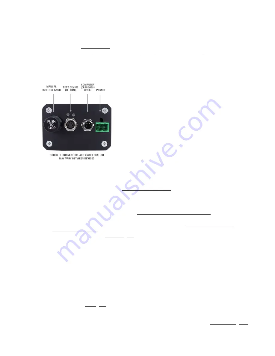
Power up all integrated devices and controllers and daisy chain them together using the RS-232
"Prev" and "Next" connectors (see  Daisy-Chaining Devices for more details). Many products share
power through the daisy-chain cables. The power indicator on each should light up.

1. 

Turn the knob to move a device. Most devices will only move in one direction until they reach a home
sensor at one limit of travel. Then they will move in both directions over full travel.

2. 

Download and install Zaber Console from http://www.zaber.com/wiki/Software. Start Zaber Console
and select the communications port the first controller is connected to. For instructions on how to find
the available communication ports on your system, please refer to: Appendix A - Available
Communications Ports.

3. 

From the Console, issue a renumber (T:2) command to all devices (Zaber Console may prompt you to
do this also). The first device in the chain (closest to the computer) will become Device 1, the next
will become Device 2, and so on.

4. 

Initialization

Every time the device is powered up or reset, the device should be returned to the home position. This is
achieved by sending the home (T:1) command to the individual unit or all units. Until this is done, most
devices will only allow motion in one direction, towards the sensor.

If it is not possible in your application to home the device after every power-up, see the tools parking (T:65)

 Quick Tutorial

4

Summary of Contents for X-LRQ-DEC Series

Page 1: ...EC Product User s Manual Firmware 5 00 and up Last Update November 2 2016 Visit www zaber com wiki for more recent updates Zaber Technologies Inc 2 605 West Kent Ave N Vancouver British Columbia Canada V6P 6T7 ...

Page 2: ...aisy Chaining Devices 9 Physical Installation 11 Dust Cover Removal and Installation 11 Manual Control 14 Velocity Mode 14 Displacement Mode 14 Summary of knob functionality 14 Trajectory Control and Behaviour 15 Software Position Limits 15 Movement Speed 15 Quick Command Reference 16 ASCII Protocol 16 Quick Commands 16 Quick Device Settings 17 Binary Protocol 19 Troubleshooting X Series Motion De...

Page 3: ...6 Standard products 26 Custom products 26 How to return products 26 Email Updates 27 Contact Information 28 Appendix A Available Communications Ports 29 Finding Installed Serial Ports 29 Windows 29 Linux 29 Comparison X LRQ DEC Series 32 ii ...

Page 4: ...cal medical aviation or military applications or situations where a product s use or failure could cause personal injury death or damage to property Zaber disclaims any and all liability for injury or other damages resulting from the use of our products Disclaimer 1 ...

Page 5: ...on of linear guides The X LRQ DEC series of linear stages use recirculating ball bearing linear guides to support and guide the stage top of the device These linear guides require lubrication in order to achieve the longest possible lifetime at the highest possible performance At the rated load of the device it is recommended to re lubricate each bearing block on the linear guide at a 500 km servi...

Page 6: ...nter when using a terminal program An ASCII command followed by T xx indicates a legacy T Series Binary Protocol command that achieves the same result For example move abs 10000 T 20 10000 shows that a move abs ASCII command can also be achieved with Binary command number 20 Not all ASCII commands have an equivalent Binary counterpart Conventions used throughout this document 3 ...

Page 7: ...nd install Zaber Console from http www zaber com wiki Software Start Zaber Console and select the communications port the first controller is connected to For instructions on how to find the available communication ports on your system please refer to Appendix A Available Communications Ports 3 From the Console issue a renumber T 2 command to all devices Zaber Console may prompt you to do this als...

Page 8: ...tings Refer to the ASCII Settings or Command Reference section for detailed descriptions of each setting Command Description 1 set maxspeed 100000 T 42 100000 Set the speed of all axes on the device 1 get maxspeed T 53 42 Query the axes speed 1 system restore T 36 Restore all the settings of Device 1 to the default Built In Help Zaber X Series devices feature a built in help guide providing a quic...

Page 9: ...LE 0 01 0 move abs x Move to absolute position 01 0 move rel x Move by relative position 01 0 move vel x Move at constant velocity 01 0 move min Move to minimum position 01 0 move max Move to maximum position Built In Help 6 ...

Page 10: ...ower supply please ensure your device is grounded by connecting the negative terminal of the power connector to AC Earth RS 232 Communications Pin Previous Next 1 Power Power 2 Ground Ground 3 Receive Transmit 4 Transmit Receive Default Settings Baud Rate 115200 Protocol Zaber ASCII Specifications Supported Protocols Zaber ASCII Zaber Binary Supported Baudrates 9600 19200 38400 57600 115200 Bits 8...

Page 11: ...evice is under manual control via the knob in Velocity mode The blinking rate is proportional to movement speed Blinking at fixed rate Packet corruption has occurred for ASCII commands sent with a checksum Blue Slip Stall On The device is slipping 2 short flashes every 1 sec The stationary device has been forced out of position On Off cycle every 2 sec The device has stalled and stopped Indicators...

Page 12: ...es below 3 Install software from http www zaber com wiki Software For the initial setup using Zaber Console is recommended 4 As a simple first test try entering renumber T 2 1 home T 1 1 move rel 10000 T 21 10000 The parameter of 10000 in the move command above specifies 10000 microsteps To see the microstep size default resolution for the device and how it translates to displacement first go to t...

Page 13: ...chain closest to the computer This configuration will reduce the number of adaptor cables required Connect a T XDC or S XDC for daisy chaining an A MCB2 adaptor cable to the Next port of the last X Series device in the chain and to the Prev port of the T Series or A Series device Power supplied to an X Series device will not be transmitted to any T Series or A Series devices in the chain Contact Z...

Page 14: ...amage will occur if these T slots are used to mount the stage Dust Cover Removal and Installation Use caution handling the shim as the edges are extremely sharp For disassembly simply remove the In most cases the shim only needs to be lifted slightly to install the mounting screws and does no Move the stage at least 50mm away from one end of the LRQ base and feed the LRQ Dust Cover Shim in from on...

Page 15: ...ted and should still have a slight bend The LRQ Dust Cover Shim should be low enough that it does not contact the bottom of the LRQ Dust Cover Adapter Lid when installed but it should not be so tight that it increases the drag of the stage Drive the LRQ stage back and forth through its full length a few times and visually inspect that the Dust Cover Shim does not bulge anywhere during travel If th...

Page 16: ...r Adapter Lid and place it in position on the Stage Top Adapter ensuring that the countersink holes are on the top Take the M2x4 screws and hand tighten them into the Stage Top Adapter Dust Cover Removal and Installation 13 ...

Page 17: ... stops and resets the knob upon arriving at the end of travel Displacement Mode Turn the knob clockwise to move the device in the positive direction extend counter clockwise for negative direction retract Each detent of the knob moves the device a fixed number of microsteps specified by the knob distance T 110 setting If knob distance T 110 is set to 0 each detent of the knob will move to the next...

Page 18: ...device depends on device status and various speed settings If the device has not been initialized by the home T 1 command or by moving towards the home end of the device movement speed will be constrained to fail safe values The home status of the device can be determined by reading the limit sensor triggered T 53 setting the binary command additionally requires a value of 103 Movement speed of th...

Page 19: ... to the documentation 0 6 24 Configure linear encoder calibration estop Axis 0 6 06 Instantly stops motorized movement get Device and Axis setting value 6 06 Retrieves the current value of the device or axis setting help Device commands reply warnflags enums command enum 0 6 06 Displays the help information for the system home Axis 0 6 06 Moves the axis to the home position move Axis abs rel vel v...

Page 20: ...ion is met warnings Axis clear 0 6 06 Displays the active device and axis warnings optionally clearing them if applicable Quick Device Settings The settings listed below can be inspected and modified with the get and set commands described above Setting Scope Writable Firmware Versions Description accel Axis Yes 6 06 Sets the acceleration used to modify the speed calibration type Axis No 6 24 The ...

Page 21: ...coder pos Axis No 6 17 Position measured by encoder knob dir Axis Yes 6 06 Sets the movement direction for the knob knob distance Axis Yes 6 06 Sets how far the device moves with each step of the knob in displacement mode in units of microsteps knob enable Axis Yes 6 06 Disable the use of the knob when set to 0 knob maxspeed Axis Yes 6 06 The maximum speed that can be reached using the knob in vel...

Page 22: ...em serial Device No 6 15 The serial number of the device system voltage Device No 6 06 The voltage being applied to the device version Device No 6 06 The firmware version of the device version build Device No 6 17 The build number of the device s firmware Binary Protocol The following table offers a quick command reference for the X LRQ DEC For convenience you may sort the table below by instructi...

Page 23: ... Alias Number 48 Alias Number Setting Alias Number Return Device ID 50 Ignored Read Only Setting Device ID Return Firmware Version 51 Ignored Read Only Setting Version Return Power Supply Voltage 52 Ignored Read Only Setting Voltage Return Setting 53 Setting Number Command Setting Value Return Status 54 Ignored Read Only Setting Status Echo Data 55 Data Command Data Return Firmware Build 56 Ignore...

Page 24: ...e Setting Velocity Scale Set Knob Velocity Profile 112 Velocity Profile Setting Velocity Profile Set Acceleration Only 113 Acceleration Setting Acceleration Set Deceleration Only 114 Deceleration Setting Deceleration Set Move Tracking Mode 115 Tracking Mode Setting Tracking Mode Set Manual Move Tracking Disabled Mode 116 Tracking Mode Setting Tracking Mode Set Move Tracking Period 117 Tracking Per...

Page 25: ...utside of the recommended range This will occur when the supply voltage is either over or under the recommended range the internal temperature has exceeded the set limit or the driver has disabled Check the following The input voltage is within the operational range of the device This can be read from the device with the get system voltage command The device temperature is within range This can be...

Page 26: ...ng travel and is frequently slipping This condition happens if the thrust needed is more than the thrust available from the device Check the following The force on the device is less than the maximum thrust The voltage matches the specified voltage Read the voltage using the get system voltage command Voltage less than the specified voltage for the device will reduce the device s maximum thrust Te...

Page 27: ...ol characters such as line feed and spaces That the serial port is not configured with a termination character it often defaults to linefeed If problems are encountered when using custom software try using one of the demo programs from the Zaber website to verify that the hardware works The device does not behave as expected when software sends it a series of commands The computer might be set to ...

Page 28: ... operating it under statically noisy environment The device makes noise but does not move The Blue LED is flashing The device is stalling Try removing all external loads If the device now extends and retracts normally the problem is excessive load Try to reduce the load and ensure the load is less than the maximum thrust A higher thrust or torque can be achieved by lowering the speed of the device...

Page 29: ...roducts with faults due to manufacturing defects free of charge Custom products Custom products are any part numbers containing the suffix ENG followed by a 4 digit number Each of these products has been designed for a custom application for a particular customer Custom products are guaranteed for one year unless explicitly stated otherwise During this period Zaber will repair any products with fa...

Page 30: ...d like to receive our periodic email newsletter including product updates and promotions please sign up online at www zaber com news section Newsletters typically include a promotional offer worth at least 100 Email Updates 27 ...

Page 31: ...oll free in North America Fax 1 604 648 8033 Mail 2 605 West Kent Ave N Vancouver British Columbia Canada V6P 6T7 Web www zaber com Email Please visit our website for up to date email contact information The original instructions for this product are available at http www zaber com wiki Manuals X LRQ DEC Contact Information 28 ...

Page 32: ...tegory In this example there are two serial ports available COM1 and COM15 which are both USB adaptors 2 Linux Finding devices Open a terminal and execute the following command dmesg grep E ttyU S The response will be similar to the following 2 029214 serial8250 ttyS0 at I O 0x3f8 irq 4 is a 16550A 2 432572 00 07 ttyS0 at I O 0x3f8 irq 4 is a 16550A 1 Appendix A Available Communications Ports 29 ...

Page 33: ... user has to be root or a member of the dialout group to be able to access these devices crw rw 1 root dialout 4 64 Oct 31 06 44 dev ttyS0 crw rw 1 root dialout 4 68 Oct 31 06 45 dev ttyS4 crw rw 1 root dialout 188 0 Oct 31 07 58 dev ttyUSB0 2 Checking group membership groups The output will be similar to the following adm cdrom sudo dip plugdev users lpadmin sambashare Notice that dialout is not ...

Page 34: ...xed knob provides convenient manual control for versatile operation even without a computer These stages connect to the RS 232 port or USB port of any computer and they can be daisy chained with any other Zaber products The daisy chain also shares power making it possible for multiple X Series products to share a single power supply Convenient locking 4 pin M8 connectors on the unit allow for secu...

Page 35: ...n M8 Mechanical Drive System Precision lead screw Limit or Home Sensing Magnetic home sensor Manual Control Indexed knob with push switch Axes of Motion 1 LED Indicators Yes Mounting Interface M6 and M3 threaded holes Vacuum Compatible No Operating Temperature Range 0 to 50 degrees C RoHS Compliant Yes CE Compliant Yes Stiffness in Pitch 640 N m deg 27 microrad N m Stiffness in Roll 1850 N m deg 9...

Page 36: ...om 0 000138 X LRQ450AL DE51C 0 09921875 microm 450 mm 17 717 13 µm 0 000512 2 5 microm 0 000098 X LRQ450BL DE51C 0 49609375 microm 450 mm 17 717 15 µm 0 000591 3 5 microm 0 000138 X LRQ600AL DE51C 0 09921875 microm 600 mm 23 622 13 µm 0 000512 2 5 microm 0 000098 X LRQ600BL DE51C 0 49609375 microm 600 mm 23 622 15 µm 0 000591 3 5 microm 0 000138 Part Number Backlash Maximum Speed Minimum Speed Spe...

Page 37: ...al Runout Pitch X LRQ075AL DE51C 110 N 24 7 lb 190 microm 0 007480 31 microm 0 001220 0 034 degrees 0 593 mrad X LRQ075BL DE51C 100 N 22 4 lb 190 microm 0 007480 31 microm 0 001220 0 034 degrees 0 593 mrad X LRQ150AL DE51C 110 N 24 7 lb 190 microm 0 007480 31 microm 0 001220 0 034 degrees 0 593 mrad X LRQ150BL DE51C 100 N 22 4 lb 190 microm 0 007480 31 microm 0 001220 0 034 degrees 0 593 mrad X LR...

Page 38: ...ees 0 768 mrad 6 35 mm 0 250 3 77 kg X LRQ450AL DE51C 0 041 degrees 0 715 mrad 0 065 degrees 1 134 mrad 1 27 mm 0 050 4 61 kg X LRQ450BL DE51C 0 041 degrees 0 715 mrad 0 065 degrees 1 134 mrad 6 35 mm 0 250 4 61 kg X LRQ600AL DE51C 0 054 degrees 0 942 mrad 0 075 degrees 1 309 mrad 1 27 mm 0 050 5 41 kg X LRQ600BL DE51C 0 054 degrees 0 942 mrad 0 075 degrees 1 309 mrad 6 35 mm 0 250 5 41 kg Part Nu...

Page 39: ...02 s X LRQ075BP DE51C 11 microm 0 000433 205 mm s 8 071 s 0 000303 mm s 0 000012 s 0 000303 mm s 0 000012 s X LRQ150AP DE51C 8 microm 0 000315 40 mm s 1 575 s 0 000061 mm s 0 000002 s 0 000061 mm s 0 000002 s X LRQ150BP DE51C 11 microm 0 000433 205 mm s 8 071 s 0 000303 mm s 0 000012 s 0 000303 mm s 0 000012 s X LRQ300AP DE51C 8 microm 0 000315 40 mm s 1 575 s 0 000061 mm s 0 000002 s 0 000061 mm ...

Page 40: ...07480 31 microm 0 001220 0 034 degrees 0 593 mrad X LRQ450AP DE51C 110 N 24 7 lb 200 microm 0 007874 62 microm 0 002441 0 076 degrees 1 326 mrad X LRQ450BP DE51C 100 N 22 4 lb 200 microm 0 007874 62 microm 0 002441 0 076 degrees 1 326 mrad X LRQ600AP DE51C 110 N 24 7 lb 210 microm 0 008268 77 microm 0 003031 0 097 degrees 1 693 mrad X LRQ600BP DE51C 100 N 22 4 lb 210 microm 0 008268 77 microm 0 00...

Page 41: ...RQ450AP DE51C 0 041 degrees 0 715 mrad 0 065 degrees 1 134 mrad 1 27 mm 0 050 4 78 kg X LRQ450BP DE51C 0 041 degrees 0 715 mrad 0 065 degrees 1 134 mrad 6 35 mm 0 250 4 78 kg X LRQ600AP DE51C 0 054 degrees 0 942 mrad 0 075 degrees 1 309 mrad 1 27 mm 0 050 5 58 kg X LRQ600BP DE51C 0 054 degrees 0 942 mrad 0 075 degrees 1 309 mrad 6 35 mm 0 250 5 58 kg Comparison X LRQ DEC Series 38 ...

Reviews: