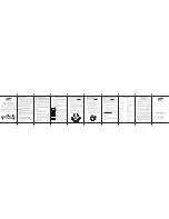
1) Release front cover by inserting a flat screw-driver into side crack
3) Mount back part into junction box, then screw the thermostat in
2)
Release the frame
4) Re-install the frame and the front part in sequences
Installation
2. Remove the display unit and backplate of the device from the packaging.
3. FIRST ENSURE THE POWER IS OFF at the main circuit breaker, and then test the wires with a probe or multimeter to verify.
Insert the power and heater wires to the correct device terminals by inserting a small Phillips-head screwdriver in the slot beneath
each terminal to open. Follow the connection diagram and instructions below:
• Power wires:
connect Line & Neutral wires to L & N terminals labeled “IN”
• Heater wires:
connect Line & Neutral wires to L & N terminals labeled with “heating element” graphic
WARNING: The wire size shall be in compliance with regulations, using wire with insufficient size for big load will cause
severe temperature rising.
This device should be installed by a licensed electrician in a manner that conforms to local regulations and building codes.
Provide these instructions to the licensed electrician who is installing the device.
WARNING: Electrical power must be switched off during installation.
1. Placement of the device is of utmost importance for proper operation and must be away from sunlight and sources of direct
heat. We recommend installing the device approximately 1.5 meters above the floor.
Troubleshooting:
1. External (floor) sensor temperature tolerance is too big
Possible reason: the selected sensor type is not correct
2. The gateway can not set temperature when energy save mode is selected
The temperature schedule (parameter 8) of auto mode (energy save mode) is not configured correctly
3. Current temperature is not executed when away mode is selected
Check whether away mode time is set as 0 or within valid time range
4. Over heat alarm when power on the device
Possible reason: the set sensor type is not correct or sensor type after factory reset is not correct
5. Device time is not the same as the gateway controller after included to the network
Set the device time and time zone manually after included to the gateway network
6. The tolerance of the indoor temperature sensor is high after powered on
Possible reason: due to temperature effect, we need to wait for a while
Wiring diagram
NTC
L L N N
L
N
Floor temp
sensor
Connection diagram 2
SR-ZV9092A
Window open detect function temperature threshold: the Celsius degrees that the
temperature decreases within 3 minutes, unit is 0.5 Celsius degree.
0, disbaled
3-8, the set temperature threshold
0x18(24)
1
0
Other Set
0x1A(26)
1
0
Monitor Set
The time zone that the time parameters command adopts is UTC, the time zone
need to be set:
+12 ~ -12
NTC
L L N N
SR-ZV9092A
L
N
Connection diagram 1
Floor temp
sensor