background image


- 7 - 


2.1.2 Emergency Button 

In the case of emergencies, push the emergency button (see Figure 7) to 

stop  the  motion  system  immediately.  To  restart  the  system,  rotate  the 

button clockwise as indicated. 


Figure 7.The Emergency Button 

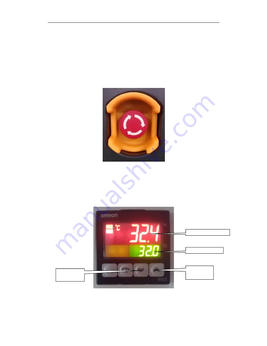
2.1.3 Temperature Controller 

To control the temperature of the build chamber. 


Figure 8. The Temperature Controller 

Note: 

The standard recommended temperature setting is 32

.


However,


Set temperature 

Current temperature 

Increase the 

temperature 

Decrease the 

temperature 

Summary of Contents for SL series

Page 1: ...SL series 3D Printer User s Manual Z Rapid Technologies Co Ltd Ver 1 0...

Page 2: ...on 7 2 1 3 Temperature Controller 7 2 1 4 Monitor 8 2 1 5 Buttons Alarm Speaker 8 2 1 6 Laser Controller Cabinet 8 2 1 7 Main Power Switch 10 2 2 Start Stop SL 10 2 2 1 Start SL 10 2 2 2 Stop SL 11 3...

Page 3: ...t from the data provided by the build data file As the laser contacts the resin the beam photo polymerizes the resin into a solid When a layer is completed an elevator lowers the part deeper into the...

Page 4: ...2 sandblasting painting or dyeing Z Rapid standard range of SL Production Systems includeSL300 SL450 and SL600 see Figures 1 2 and 3 Figure 1 SL300 Figure 2 SL450...

Page 5: ...cteristic High speed printing High quality printed parts User friendly Highly automated 1 3 The SL Process There are three major steps in stereolithography CAD Preparation Print Process and Post Proce...

Page 6: ...Print Process Turn on the machine and copy all the SLC files into the PC Add Part slc file into the Zero build software The s_part slc will be added automatically Position the parts on the build plate...

Page 7: ...imilar on the SL600 2 1 1 Build Chamber The build chamber see Figure 5 is the working space of the SL Production Systems and it encompasses the build plate recoater resin vat etc The build plate is th...

Page 8: ...ting Figure 5 The Build Chamber The resin vat see Figure 6 is located below the build plate and contains resin Figure 6 The Resin Vat Note Open the vat access door to locate the tap for draining out r...

Page 9: ...e system rotate the button clockwise as indicated Figure 7 The Emergency Button 2 1 3 Temperature Controller To control the temperature of the build chamber Figure 8 The Temperature Controller Note Th...

Page 10: ...PC Control system etc d Laser On On Off button for the laser controller e Heater On On Off button for the heater system f Light On On Off button for the LED lights in the build chamber g Alarm Speake...

Page 11: ...ting instructions for the RFH Laser and Inngu Laser are detailed in Appendix 1 and Appendix 2 respectively Figure 10 RFH Laser Controller Panel Figure 11 Inngu Laser Controller Panel Caution Avoid loo...

Page 12: ...ain Power Switch Important Please ensure that the machine is properly grounded before switching on or it may damage the laser system or the electrical components 2 2 Start Stop SL 2 2 1 Start SL a Tur...

Page 13: ...el of your laser system d Push the Laser On button to turn off the laser system e Push the Control On button to turn off the control system f Turn the main power switch anti clockwise to shut down the...

Page 14: ...ter You will see the Zero icon on the desktop of OS Double click on the icon and the Zero interface window see Figure 13 pops up Figure 13 Zero Interface Ctrl click on numbering for feature details 1...

Page 15: ...LC files Save Save the added files as a project The project will contain the part placement information for convenience when repeating the print project Open Open a project file Part Dimensions Displa...

Page 16: ...re will automatically centralize the added files parts to be printed on the build plate Offset refers to the distance between the parts Click on the Do button to execute the Auto Distribute command b...

Page 17: ...of the original part This function will not delete original part f Close Close the window and automatically save any changes made 2 Tools Bar Figure 15 Tools Bar New New project Open Open project Save...

Page 18: ...s compensate feature Note Do not select this function if printing with raft or if finished part needs to be polished b Precise mode High resolution printing function c Rapid mode Quick printing functi...

Page 19: ...wards Level in R Axis indicates the resin level value measured by sensor Coating Axis Control the movement of recoater used to sweep the resin forwards or backwards Stir Move the build plate upwards a...

Page 20: ...In the Coating Axis the button moves the recoater forwards towards the user c To move the build plate resin plunger recoater to specified distances 0 5mm 2mm or user specified distance d This button...

Page 21: ...downwards Move 10 layers downwards Bottom layer Move to user specified layer Move the view Zoom in Zoom out Zoom in selected scope Default view Show the name of the files Laser Power Quality switch La...

Page 22: ...s the resin level 6 Layer Frame Shows the total layers of build project and layer currently printing Figure 22 Layer Frame 7 Build Parameters Including Scan Speed Parameters Z Axis Parameters Coating...

Page 23: ...ld plate moves after laser scans a layer Post Delay The delay before the build plate moves up for scanning the next layer Auto Uprise To set timing for the build plate to be raised automatically after...

Page 24: ...inting Step a Click on to add SLC files b Click the edit see Figure 23 button in Build Project File to position parts for printing Figure 23 Build Project File Frame c Click on start to print d The al...

Page 25: ...vel indicator in the Platform window and top up resin if level is low Note Please clean the build platform to remove remnants of cured resin after each print job as these remnants will affect the next...

Page 26: ...Drain excess liquid resin from the finished part for several minutes c Parts can be ruined by excessive exposure to air moisture cleaning solvent or light 4 1 Cleaning the parts You may use ethyl alc...

Page 27: ...polishing You may sandblast or polish the surface of the printed part if required This improves the quality of the surface finishing and dimension For polishing you may use sandpaper 600 to 800 grit s...

Page 28: ...n and lubricate according to Z Rapid technical support instructions 2 Contact Z Rapid technical support Heater does not work 1 Fuse has blown 2 Loose cables 1 Replace fuse 2 Secure all connections und...

Page 29: ...chnologies Co Ltd Tel 0512 63398240 63398241 0512 63398242 63398243 Website www zero tek com Leave a message on our website Fax 0512 63398290 Email tech zero tek com Address No 13 Tongan Road West Suz...

Page 30: ...to turn on the laser system Open the laser controller cabinet door On the laser controller turn on the power button and turn the key switch to the On position Wait for about 10 minutes for laser to s...

Page 31: ...to operate the laser controller Tips If the red light does not turn off please shut down the laser system and restart it after 10 seconds Please contact Z Rapid technical support if the red light cont...

Page 32: ...ical carriage returns to zero position after the test If no errors are found after the test the system may be started by switching the key to the position of ON Appendix figure 2 Self test It takes tw...

Page 33: ...ower has the attenuating property and the power value is important for solidifying the parts If necessary under guidance by Z Rapid technical support you may change some parameters to adjust the laser...

Page 34: ...t functions Place the cursor on the selected function and press ENTER button to display that function s sub menu Setting parameters in the QS Setting interface Appendix figure 5 QS Setting Parameters...

Page 35: ...e asked if modified parameters should be saved as shown below Appendix Figure 6 ENTER Confirm to save changes and parameters will be stored into the ROM of the system ESC Changes will not be saved and...

Page 36: ...ME button to return to HOME window This operation will not save the modified parameters into the ROM of the system If modifications need to saved press ESC button in the MENU window to display the Sav...

Page 37: ...h located at the back of the laser controller to power on the laser system Please preheat for about 10 minutes if the laser has not been switched on for a prolonged period of time and then turn on the...

Page 38: ...List of Front Panel Controls Num Description Function 1 QS EXT Select the Q switch triggering mode either External or Internal When lit on it is External triggering 2 QS ON Turn ON or OFF Q switch Whe...

Page 39: ...the up and down arrow to change the settings through software 12 EMERGENCY OFF Shut down the laser in case of emergency 13 POWER ON LED light on indicates the laser controller is power on 14 KEY SWITC...

Reviews: