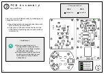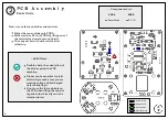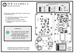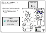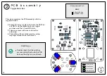
PCB Assembly
Resistors & Inductors
2
7
Previous Steps
Ground Pins
Solder Joints
Components
R13
R14
R15/R16
R17
R18/R19
330k
10k
150k
56k
2.2k
L1/L2
R8
R9
R10
R12
47uH
1M
6.8k
560r
47k
PCB A
R1
R2
R3/R6
R4/R5
300k
150k
1G
68M/60M
PCB B
~ Components List ~
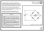
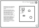
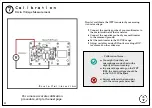
Learn how to match resistors with a
method described on the next page!
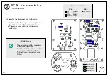
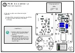
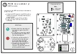
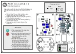
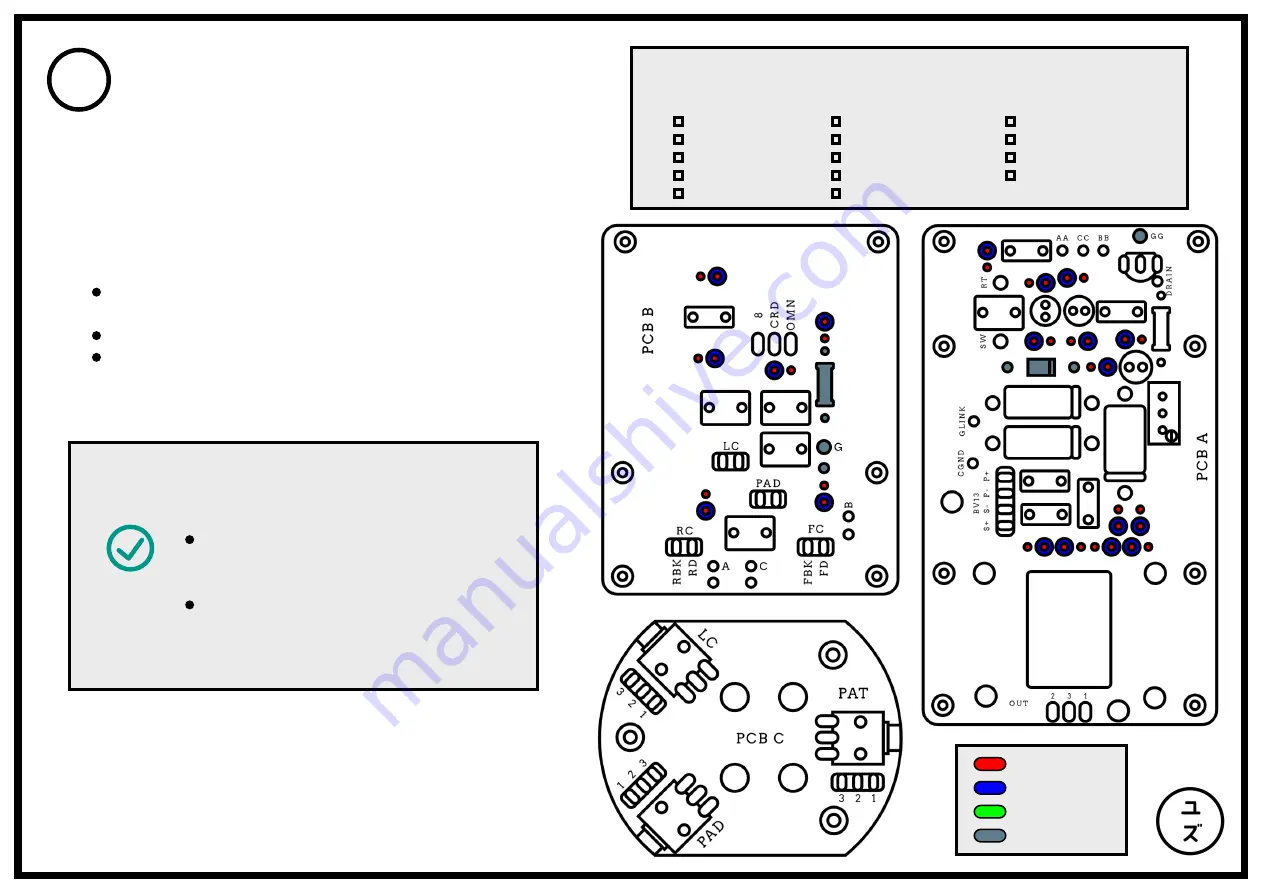
In this step, we finish soldering the resistors along
with the inductors:
Solder all the remaining resistors to their
corresponding locations.
Solder inductors L1/L2 onto PCB A.
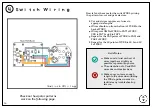
Trim any excess with wire cutters after
soldering.
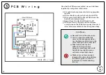
Use a bender tool or some needle
nose pliers to bend the resistors
in shape for a nice finish.
Make sure the component rests
vertically on the side marked by
a larger circle on the PCB.
~ Build Notes ~


