!
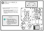
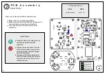
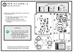
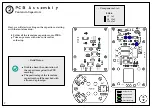
PCB Assembly
JFET Transistor
2
12
Previous Steps
Ground Pins
Solder Joints
Components
R11
JFET
25k Trimmer
Transistor
PCB A
~ Components List ~
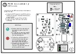
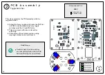
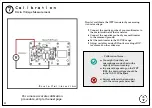
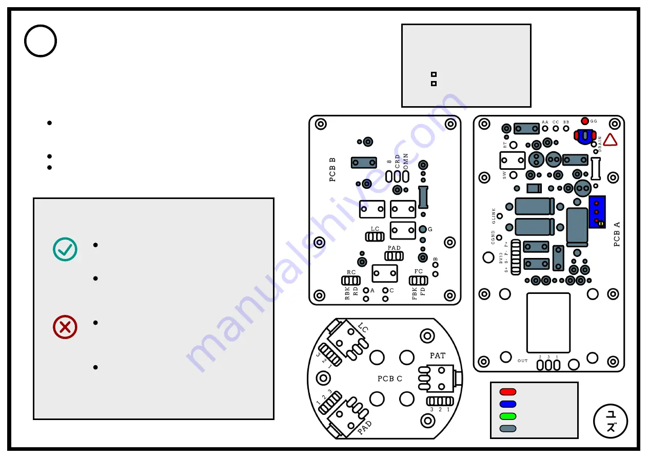
Let's focus on the JFET transistor and the trimmer
resistor for now:
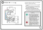
Solder the JFET transistor onto PCB A with its
middle pin (the gate terminal) lifted towards
ground pin GG.
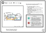
Solder variable resistor R11 onto PCB A.
Trim any excess with wire cutters after
soldering.
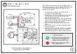
Double-check the orientation of
the transistor against the PCB
marking.
You may have to bend the middle
pin of the trimmer to make it fit
into the through-hole.
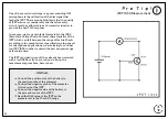
Transistors can be sensitive to
static electricity so make sure
you are wearing cotton and
discharged before handling it.
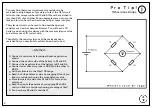
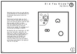
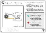
Do not use the through-hole on
the PCB when lifting the
transistor leg and solder directly
onto the isolation turret.
~ Build Notes ~


