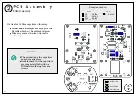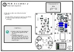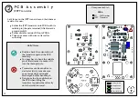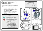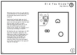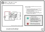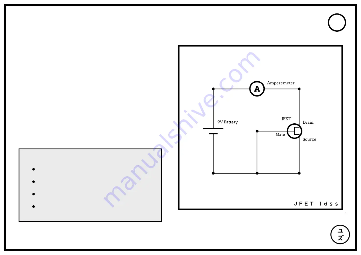
Connect the positive side of the battery to
the positive probe of the ammeter.
Connect the negative probe of the ammeter
to the drain of the JFET.
Connect the negative side of the battery to
the gate and source of the JFET.
Read the IDSS value of the JFET on the
ammeter set to the 20mA DC range.
~ Method ~
One of the most crucial steps to a great-sounding U87
microphone is the calibration of the bias signal that
feeds the JFET. The reason behind this is that the quality
of JFETs can vary considerably and therefore every
circuit must be calibrated to each transistor in order to
provide the best THD response.
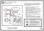
In our case, we are particularly interested in the IDSS
(Zero-Gate Voltage Drain Current) characteristics of the
JFET which can fall between the range of 2mA to 20mA
according to the manufacturer specifications. In general
for microphone applications, we are aiming for a rather
low JFET IDSS in order to obtain the best dynamic range
before distortion.
The JFET provided in your kit has already been selected
with a low IDSS but if you are curious to know the
measurement procedure, here is how.
24
!
Pro Tip!
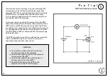
JFET IDSS Measurement

