26
GoCart200 Omni Service Manual
9.1 Motor
For motor maintenance, refer to the following procedures.
1. Unscrew 20 points and remove COVER_BTM_WATER_PROOF (⑥,
"Fig. 9: Disassemble Covers for
2. Disconnect 3 cables (motor, encoder for FuSa, and thermistor temperature sensor).
3. After unscrewing 8 points, remove WHEEL_MECANUM_ASSY_RIGHT or WHEEL_MECANUM_ASSY_
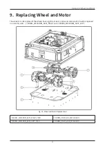
"Fig. 16: Wheel and Motor Replacement" on page 23
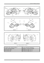
4. After releasing nuts and screws like
"Fig. 18: Wheel and Motor Assembly" on page 25
, remove
MOTOR-MT28_RIGHT_ASSY or MOTOR-MT28_LEFT_ASSY.
5. Unscrew 2 points and remove 2 units assembled ① SENSOR_PM-F45_PM-R45_ENCODER_R.
6. Like VIEW “A” and view “B”, disassemble parts ⑤ SHAFT_MAIN_MOTOR_MECAWHEEL and ⑥
BRACKET_FIX_MOTOR_MECAWHEEL in order and remove the motor.
7. Replace the unit with a new one.
•
The left motor and the right motor are different parts. Check the shape of the part before the
assembly.
9.2 9.2. Wheel
For wheel maintenance, a forklift or similar tool might be needed. Refer to the following procedures.
1. Unscrew 20 points and remove COVER_BTM_WATER_PROOF (⑥,
"Fig. 9: Disassemble Covers for
2. Disconnect 3 cables (motor, encoder for FuSa, and thermistor temperature sensor).
3. After unscrewing 8 points, remove WHEEL_MECANUM_ASSY_RIGHT or WHEEL_MECANUM_ASSY_
"Fig. 16: Wheel and Motor Replacement" on page 23
4. After releasing nuts and screws like
"Fig. 18: Wheel and Motor Assembly" on page 25
, remove
MOTOR-MT28_RIGHT_ASSY or MOTOR-MT28_LEFT_ASSY.
5. Like VIEW “C” and view “D”, after unscrewing 12 points remove WHEEL_MECA_MAIN_ASSY_RH or
WHEEL_MECA_MAIN_ASSY_LH.
6. Replace the unit with a new one.
•
The left wheel and the right wheel have different parts. Check the shape of the part again before the
assembly.
9.3 Encoder Sensor and Encoder Disk
For Encoder Sensor and Disk r maintenance, refer to the following procedures.
1. Unscrew 20 points and remove COVER_BTM_WATER_PROOF (⑥,
"Fig. 9: Disassemble Covers for
2. Disconnect 3 cables (motor, encoder for FuSa, and thermistor temperature sensor).
3. After unscrewing 8 points, remove WHEEL_MECANUM_ASSY_RIGHT or WHEEL_MECANUM_ASSY_
"Fig. 16: Wheel and Motor Replacement" on page 23
4. After releasing nuts and screws like
"Fig. 18: Wheel and Motor Assembly" on page 25
, remove
MOTOR-MT28_RIGHT_ASSY or MOTOR-MT28_LEFT_ASSY.
5. For Encoder Sensor replacement, after unscrewing 3 screws, remove ① SENSOR_PM-F45_PM-R45_
ENCODER_R.
6. For Encoder Disk replacement, after releasing 3 screws, disassemble ⑤ SHAFT_MAIN_MOTOR_
MECAWHEEL and remove ② PLATE_DISK_MAIN_ENCODER.
7. Replace the unit with a new one.


