


22
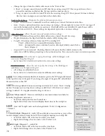
3.35 Multi-Beam Sonar
Multi-beam sonar is an option on the EcoMapper AUV. If your vehicle has a multi-beam sonar, you will operate it
from the ‘Waypoints’ section.
• Click on the box at the bottom of the ‘Waypoints’ section
that reads ‘Do not use.’
• Select the mult-beam system (Imagenex) from the
dropdown menu.
• The mult-beam sonar will now be active for this WP.
Set Physical Equipment Orientation
Users may physically orient their multibeam systems on their
instruments either looking straight down or 20 degrees to port or
starboard.
1. Select Tools>Configuration>Vehicles/
Instruments>Multibeam.
2. Select your vehicles current physical configuration.
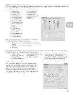
Multi-beam Options
• Gain:
Recommended between 10-14 depending on depth.
• Automatic Gain Control:
Automatically determines depth and adjust gain
accordingly for best image. Always leave this option on unless you desire to
read specifically at a predetermined depth. If you desire to make readings at
only a predetermined depth, select “Fixed Range.”
• Fixed Range:
Use if you wish to make measurements at a specific depth. Enter depth in meters in adjoining
box.
• 2X Depth Auto Range
: The range will be automatically adjusted based upon two times the depth to bottom.
• 3X Depth Auto Range
: The range will be automatically adjusted based upon two times the depth to bottom.
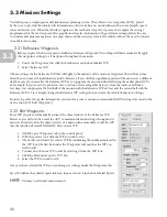
3.36 Place Waypoints
Before you place the first WP, always consider the range of the vehicle’s WiFi antenna. If possible, place the first
waypoint in WiFi range to allow recovery with manual control should any last minute changes or accidents occur.
You have two options in the ‘Tools’ section with which you may place waypoints: ‘Place Multiple Waypoints’ or ‘Place
Single Waypoint,’ which perform virtually identical functions but change the display slightly.
• ‘Place Multiple Waypoints’ draws a line as you move the cursor so that you may track exactly what line the
vehicle will take to reach the new WP. This function also displays a tooltip box identifying the distance from
the last waypoint as well as compass heading.
• ‘Place Single Waypoint’ performs the same function as ‘Place Multiple Waypoints’ but does not draw a line
until the WP is dropped. This function also does not display the tooltip box.
1. Place the crosshair cursor directly where you wish to place the first waypoint and click the left mouse button.
2. Continue to move the crosshair cursor throughout the survey area and click to add a waypoint (designated
by a numbered circle). Remember the vehicle will travel directly to the waypoint, if the vehicle surfaces and
recognizes that it missed its waypoint safety zone (within 15 feet), it will circle back and cross the waypoint
before it continues with its mission.
3. For more specific data sets, set the mission lines close together, but be sure to maintain a safe distance from
shore, shallows or any known obstacles.
4. Place the final waypoint within WiFi distance for easy retrieval via manual control. It is also prudent to
program the vehicle to ‘park’ at its final waypoint (for a reasonable time) in order to assure the vehicle
remains in the programmed end location for reliable retrieval. The first and last WPs in a mission are
designated by a square WP marker.
3.3