MAINTENANCE
CLEAN OR REPLACE AIR FILTERS REGULARLY
The intervals at which fi lters require replacement
depend on local conditions.
Under normal conditions, the room air fi lter requires
replacement every six to eight weeks. In a new build-
ing, loose dirt tracked in from the outside may shorten
this period.
To ensure proper maintenance of the fi lters, it is best
to follow an organized maintenance procedure.
MONTHLY CHECK LIST
• Inspect the unit air fi lters. Clean or replace as
required.
• Inspect the drainpan to be sure it is clean to permit
the fl ow of condensate through the drain lines.
• Inspect the fan belt for wear and alignment. Replace
or adjust as required.
YEARLY CHECK LIST
• Inspect the blower coil unit casing for corrosion and
loose fasteners.
• Inspect the blower wheel and housing. Clean if
necessary.
• Check the motor pulley and blower pulley for
alignment and tighten their set screws. Adjust belt
tension if necesssary.
• Inspect all coil connections for leaks Inspect the coil
fi ns for excessive dirt or damage. clean or repair if
required.
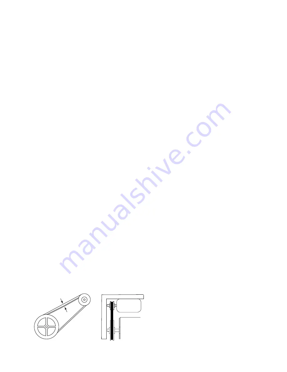
PULLEY ALIGNMENT AND BELT TENSION
Belt tension and pulley alignment should be checked.
Belt tension is adjusted by means of the motor tailpiece
adjusting bolt or the position of the motor on the base
style motor mount. A defl ection of about 3/4” to 1”
per foot of span should be obtained by pressing the
belt fi rmly
(see Figure 6)
The adjusting bolt should
be locked in position after the adjustment is made.
Alignment of pulley grooves is made by locating the
motor pulley on the motor shaft or by moving the
entire motor along the motor mounting bracket. For
blower speed adjustment, refer to that section.
BLOWER
Inspect the bearings for wear. They are ball bearing,
self-aligning and grease packed. Replace if required.
Inspect the thrust collars for end play and alignment
of wheel. Check the blades for accumulations of dirt
and clean in order to avoid imbalance and vibration.
Check mounting brackets, base bolts and isolation
material.
MOTOR
Check motor connections to ensure that they are secure
and made in accordance with the wiring diagram.
The blower motor should be cleaned annually and if it
has oiling ports, it should be oiled with a good grade
of SAE 20 oil. Normally a few drops of oil in each
bearing is suffi cient.
COIL
Any dust or other contaminants, which accumulate on
the heat transfer surfaces, interferes with the airfl ow
and impairs heat transfer. The coil must be kept clean
by any of the following methods:
• Cleaning with low-pressure compressed air.
• Flushing or rinsing with water (a detergent is
advisable for greasy surfaces).
• If strainers are installed in the valve packages,
clean the strainers once a year per manufactures
directions.
FILTER
The air fi lter should be cleaned or replaced as often as
necessary to prevent restriction of air fl ow. Always
replace the fi lter with the same type as originally
furnished.
To clean permanent fi lters, remove the fi lter and wash
in water to remove the old fi lter oil. Rinse in clean, hot
water and allow to dry. Recoat both sides of the fi lter
with RP fi lter coat, or an equivalent. Allow to drain
and dry thoroughly before reinstalling the fi lter.
DRAIN PIPING
The drain should always be connected or piped to an
acceptable disposal point sloped away from the unit.
Check the drain line for restrictions or blockage before
summer operation and monthly during the cooling
season.
DRAIN PAN
The drain pan should be clean to allow proper conden-
sate fl ow. Remove any accumulation of residue from
the drain pan and inspect for rust and leaks.
3/4" to 1" PER
FOOT OF SPAN
PULLEY ALIGNMENT
FIG 6 - PULLEY ALIGNMENT AND BELT
ADJUSTMENT
7
YORK INTERNATIONAL
FORM 115.22-NOM5 (704)


