background image

GENERAL DIMENSIONS

MODEL

UNIT CABINET

BLOWER OUT-

LET

RETURN DUCT 

CONNECTION

FILTER SIZE

MANIFOLD

CONNECTION

AA

BB

CC

EE

FF

GG

HH

90YSHW4

52-1/2

54

27

16-3/8

19-1/8

45

25-1/4

24 X 25 (2)

1-1/8 ODS.

120YSHW4

52-1/2

57

32

16-3/8

19-1/8

48

30-1/4

26 X 29 (2)

1-3/8 ODS.

180YSHW4

56-1/2

66

39-1/2

16-3/8

44-3/4

57

37-3/4

20 X 36.5 (2)

1-3/8 ODS.

240YSHW4

62-1/2

66

52

16-3/8

44-3/4

57

50-1/4

20 X 49 (3)

1-3/8 ODS.

90YSHW6

52-1/2

54

27

16-3/8

19-1/8

45

25-1/4

24 X 25 (2)

1-1/8 ODS.

120YSHW6

52-1/2

57

32

16-3/8

19-1/8

48

30-1/4

26 X 29 (2)

1-3/8 ODS.

180YSHW6

56-1/2

66

39-1/2

16-3/8

44-3/4

57

37-3/4

20 X 36.5 (3)

1-3/8 ODS.

240YSHW6

62-1/2

66

52

16-3/8

44-3/4

57

50-1/4

20 X 49 (3)

1-3/8 ODS.

4 ROW COIL

FILTER SIZE

LIQUID 

(SWEAT)

SUCTION 

(SWEAT)

90YSHX4

52-1/2

54

27

16-3/8

19-1/8

45

25-1/4

24 X 25 (2)

5/8 ODS.

1-1/8 ODS.

120YSHX4

52-1/2

57

32

16-3/8

19-1/8

48

30-1/4

26 X 30 (2)

1/2 ODS.

7/8 ODS.

180YSHX4

56-1/2

66

39-1/2

16-3/8

44-3/4

57

37-1/4

37-1/2 X 20 (3)

5/8 ODS.

1-1/8 ODS.

240YSHX4

62-1/2

66

52

16-3/8

44-3/4

57

50-1/4

50 X 20 (3)

5/8 ODS.

1-1/8 ODS.

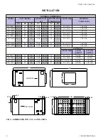
FIG 5 -  DIMENSIONS FOR 7-1/2 - 20 TON UNITS

INSTALLATION

EE

BB

FF

3.50

GG

HH

3.50

3.50

2.00

L

AIR FLOW

3.50

1.00

AIRFLOW

AA

CC

YORK INTERNATIONAL

6

FORM 115.22-NOM5 (704)

Summary of Contents for YSHW

Page 1: ...ION RECORD THE UNIT MODEL AND SERIAL NO IN THE SPACE PROVIDED RETAIN FOR FUTURE REFERENCE Model No _____________________ Serial No ___________________ INSTALLER S RESPONSIBILITY Installer Please Note...

Page 2: ...lding construction provisions for mounting the unit must be made by the contractor according to architects drawings Before mounting unit remove red headed shipping bolts and metal bush ing at blower b...

Page 3: ...in the proper level This will ensure that the condensate will drain from the unit POWER WIRING All wiring must comply with the local and national code requirements Units are provided with wiring diagr...

Page 4: ...valves throughout the building CONTROL WIRING These blower coil units can be provided with an optional class 2 relay transformer for 24 volt control circuits 3 4 HP maximum load rating Should any add...

Page 5: ...12 1 4 10 7 8 27 1 2 16 1 4 16 X 16 3 7 8 ODS 48YSHW6 39 43 1 2 38 22 7 8 13 5 8 11 7 8 29 20 1 4 16 X 20 3 7 8 ODS 60YSHW6 42 50 1 2 45 22 7 8 16 13 7 8 36 20 1 4 20 X 20 2 1 1 8 ODS 4 ROW COIL FILT...

Page 6: ...19 1 8 48 30 1 4 26 X 29 2 1 3 8 ODS 180YSHW6 56 1 2 66 39 1 2 16 3 8 44 3 4 57 37 3 4 20 X 36 5 3 1 3 8 ODS 240YSHW6 62 1 2 66 52 16 3 8 44 3 4 57 50 1 4 20 X 49 3 1 3 8 ODS 4 ROW COIL FILTER SIZE L...

Page 7: ...packed Replace if required Inspect the thrust collars for end play and alignment of wheel Check the blades for accumulations of dirt and clean in order to avoid imbalance and vibration Check mounting...

Page 8: ...just as required Check all electrical connections for tightness Review electrical print for correct wiring Check condensate drain trap Main coil drain pan and auxiliary floor drains must be properly t...

Reviews: