INSTALLATION
RECEIVING .......................................................................................................................................................................... 2
STORAGE ............................................................................................................................................................................ 2
SHIPPING WEIGHTS ........................................................................................................................................................... 2
PREPARING UNIT .......................................................................................................................................................... 2 & 3
CEILING INSTALLATION................................................................................................................................................ 2 & 3
WIRING ...................................................................................................................................................................... 3 & 4
DUCTWORK ......................................................................................................................................................................... 4
PIPING ...................................................................................................................................................................... 4 & 5
DIMENSIONS ................................................................................................................................................................. 5 & 6
MAINTENANCE
........................................................................................................................................................................ 7
STARTUP
CHECKLIST .......................................................................................................................................................................... 8
TABLE OF CONTENTS
RECEIVING
Unpack the unit as close to the installation site as
practical, minimizing any possible handling damage.
When unpacking the unit, remove all securing hard-
ware straps, wires, blocks, padding, and protective
tape. Note and follow instructions on any special
packing or caution notices that may be attached to the
unit.
See Table 1 for shipping weights.
STORAGE
If the Unit is not to be immediately installed, store
it in a dry location with the motor protected against
moisture, dust, corrosion and physical damage.
UNIT ELEVATION
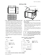
Mounting holes are provided by York for the conve-
nience of the installer
(see Figure 2)
. Threaded Rod
Hangers prove to be most desirable and effective for
mounting the unit. Rod Hangers and mounting hard-
ware are to be provided by the contractor.
Vibration isolators, if required, should be installed.
PREPARE CEILING FOR MOUNTING
Depending upon building construction, provisions
for mounting the unit must be made by the contractor
according to architects; drawings.
Before mounting unit remove red
headed shipping bolts and metal bush-
ing at blower base and blower outlet.
In addition remove, if present, the wire
tie securing motor to blower rail before
operating.
Suffi cient clearance must be provided on the side of
the blower coil to allow access to electrical controls
and to service the motor blower assembly.
Standard unit confi guration is right hand looking with
the direction of airfl ow.
It is important to ensure that the blower coil unit is
securely mounted and the structure is suffi cient to
support the weight of the equipment. On 2 to 5 ton
horizontal units, two (2) mounting rails are supplied
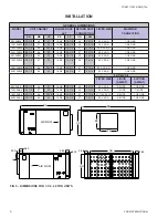
TABLE 1 - SHIPPING WEIGHTS
HORIZONTAL AIR HANDLER
SHIPPING WT. (LBS)
UNIT DESCRIPTION
UNIT MODEL
SHIPPING WT. (LBS)
UNIT MODEL
W/4 ROW COIL
W/6 ROW
COIL
2 TON HORIZ
24YSHX
185
24YSHW
185
205
3 TON HORIZ
36YSHX
215
36YSHW
205
225
4 TON HORIZ
48YSHX
250
48YSHW
240
265
5 TON HORIZ
60YSHX
320
60YSHW
290
310
7-1/2 TON HORIZ
90YSHX
400
90YSHW
450
475
10 TON HORIZ
120YSHX
525
120YSHW
490
535
15 TON HORIZ
180YSHX
775
180YSHW
670
710
20 TON HORIZ
240YSHX
835
240YSHW
835
880
INSTALLATION
YORK INTERNATIONAL
2
FORM 115.22-NOM5 (704)


