FIG 1 - HORIZONTAL UNIT MOUNTING, 2 TO 5 TON
INSTALLATION
A
B
(TOP VIEW)
AIR FLOW
MODEL
A
B
24SH
35
29
36SH
35
38-1/2
48SH
37
40
60SH
40
47
on the blower coil unit.
(see Figure 1)
All anchors for
mounting the equipment must be placed and sized to
ensure a safe and durable installation. When neces-
sary, use shims to obtain the proper level. This will
ensure that the condensate will drain from the unit.
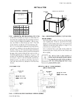
On 7-1/2 to 20 ton horizontal units, the YSHW blower
coil units are intended to be mounted thru the top of
the unit. There are 7/8” knockouts located at all four
corners top and bottom which permits fi eld supplied
hanging rods to extend through the unit to secure to
the fi eld supplied angle or channel
(see Figure 2)
All
anchors for mounting the equipment must be placed
and sized to ensure a safe and durable installation.
When necessary, use shims to obtain the proper level.
This will ensure that the condensate will drain from
the unit.
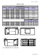
POWER WIRING
All wiring must comply with the local and national
code requirements. Units are provided with wiring
diagrams and nameplate data to provide information
required for necessary fi eld wiring
(see Figure 3 for
typical factory and fi eld wiring).
A 4 x 4 electrical box is provided on the cabinet for
connection of power supply and is located on the same
side as piping.
Any devices such as fan switches or
thermostats intended for fi eld installa-
tion must be wired in strict accordance
with the wiring diagram that is sup-
plied with the unit.
HANGING
RODS
3-1/2"
TYP
3-1/2"
TYP
YSHW/YSHX 90-240 MODELS
FIG 2 - MOUNTING WITH RODS, 7-1/2 TO 20 TON
120V-1PH-60HZ
SUPPLY
JUNCTION
BOX
OPTIONAL RELAY / TRANSFORMER
(FIELD INSTALLED)
FIELD WIRING
FACTORY WIRING
120V-1PH-60HZ
SUPPLY
JUNCTION
BOX
RELAY / TRANSFORMER
3/4 HP Max. Load Rating
N L
STANDARD UNIT
N L
FIELD WIRING
FACTORY WIRING
FIG 3 - TYPICAL FACTORY AND FIELD CONTROL WIRING
3
YORK INTERNATIONAL
FORM 115.22-NOM5 (704)


