FORM 155.32-ICOM2.EN.UL
SECTION 5 - COMMISSIONING
ISSUE DATE:1/10/2018
JOHNSON CONTROLS
83
SECTION 5 - COMMISSIONING
GENERAL GUIDELINES FOR USE
Before Operation
Charge the solution and the refrigerant water if the solution and refrigerant water is in the
barrels during the delivery.
During commissioning, check the motor’s rotating direction of the solution pump, refrigerant
pump, and purge pump.
The rotation direction can be tested by using a rotation detector (Bell and Gosset or WILO
DKG). If a rotation detector is not available, use the procedure shown below:
1. Remove the plugs at the solution and refrigerant sampling valves.
2. Make sure the valves are completely closed.
3. Confirm that the absorber and refrigerant tank contain enough solution and refriger-
ant.
4. Connect a compound gauge (NPT 1/2 of an inch) to the sampling valve with Teflon
tape.
5. Operate the pump.
6. Open the valve.
7. Read and record the delivery pressure of the solution pump and the refrigerant pump.
8. Close the valve.
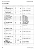
9. Check the pressure readings, see
to see if your pump rotation
is in the right direction. The correct direction shows a higher discharge pressure.
10. Remove the compound gauge.
11. Put the plugs back on the valves.
12. Clean the gauge with water.
13. For refrigerant, confirm the correct rotation by looking at the refrigerant spray through
the sight glass.
NOTE: The flow of fluid cannot be seen because the solution and refrigerant pumps are
hermetically sealed.
CAUTION: Do not run the solution pump without solution. Do not run the refrigerant
pump without refrigerant water .
NOTE: The gauge scale must be -760 mm Hg. to 2 Kg. / cm2g, or -30 inches Hg. to 30
psig. To prevent corrosion of the gauge, clean it thoroughly, and check it for leaks after
each use.
NOTE: The delivery pressure reflects the high vacuum condition of the machine. If the
inside pressure is atmospheric, add 1.0 kg / cm (14.3 psig) to the standard value found
in
Table 29 on page 76.

