FORM 155.32-ICOM2.EN.UL
SECTION 4 - TECHNICAL DATA
ISSUE DATE:1/10/2018
JOHNSON CONTROLS
79
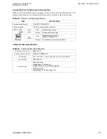
Table 25 -
Write Command
USER-CREATED
The diagrams and tables that follow detail some of the work that must be performed by the
customer to ensure that the communication systems work properly.
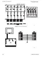
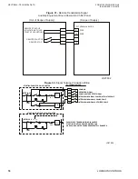
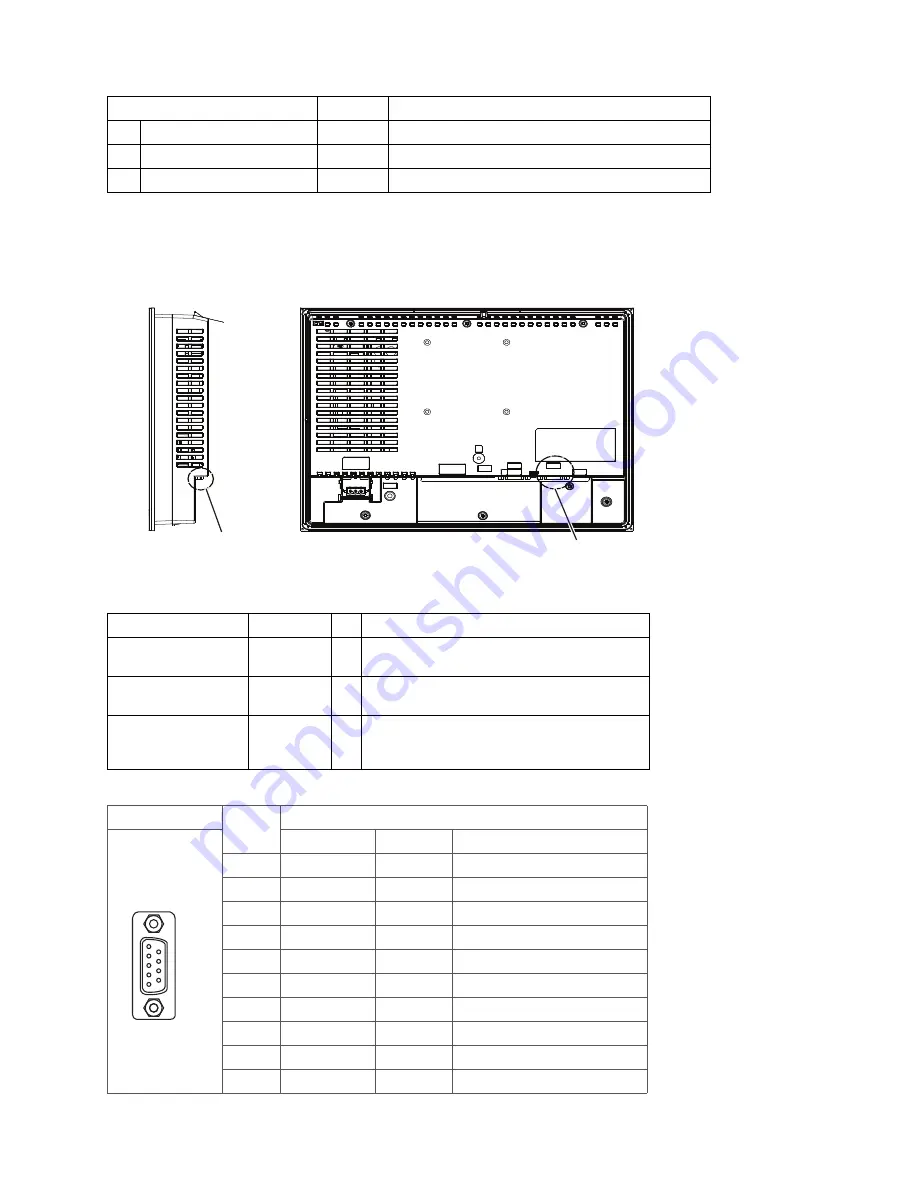
Figure 35 -
Connection Detail For Sub 9 PiN
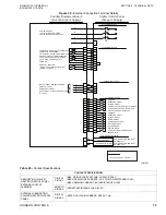
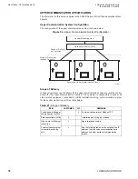
Table 26 -
Scope of Delivery of Upper Communication System
Table 27 -
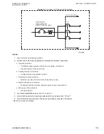
Cable Diagram (RS-422/RS485)
ITEM
ADDRESS
CONTENT
1
Chiller-heater operation signal
02001
ON at CHILLER-HEATER OPERATION, PULSE SIGNAL
2
Chiller-heater stop signal
02002
ON at CHILLER-HEATER STOP, PULSE SIGNAL
3
Set point
00203
0050~1000 unit, 1 unit=0.1°F (0.1°C)
ITEM
CUSTOMER JCI
REMARKS
Control panel with upper
communication function
X
Communication protocol: Modbus RTU
Wiring work for Modbus
RTU communication
X
Apply RS485 communication cable, see
.
Communication program
for central monitoring
unit
X
For the details of the communication protocol, path
type, function code, communication data address,
and so on.
PIN CONNECTION
PIN. NO.
RS-422/RS-485
SIGNAL NAME DIRECTION
MEANING
1
RDA
Input
Receive Data A (+)
2
RDB
Input
Receive Data B (-)
3
SDA
Output
Send Data A (+)
4
ERA
Output
Data Terminal Ready A (+)
5
SG
Signal Ground
6
CSB
Input
Send Possible B (-)
7
SDB
Output
Send Data B (-)
8
CSA
Input
Send Possible A (+)
9
ERB
Output
Data Terminal Ready B (-)
Shell
FG
Frame Ground (Common with SG)
LD20597b
Serial Interface (COM2)
Connect User Created Table
5
1
9
6
LD20598

