98
YORK INTERNATIONAL
above has a programmed CR of 42.0 - 46.0°F. The user’s
desired leaving chilled temperature (“TARGET”) will be
44.0°F or the midpoint of the CR. This midpoint tempera-
ture will be referred to as the “TARGET” temperature in
the following description.
The LOW LIMIT WATER TEMPERATURE is the mini-
mum user acceptable leaving water temperature as de-
fined by the programmed CONTROL RANGE (CR). The
LOW LIMIT WATER TEMP. must be programmed into
the Micropanel to establish the low end of the CR. In the
example above, 42.0°F is programmed.
The HIGH LIMIT WATER TEMPERATURE is the maxi-
mum user acceptable leaving water temperature as de-
fined by the programmed CONTROL RANGE (CR). In
the example above, the HIGH LIMIT WATER TEMPERA-
TURE is programmed in the CR at 46°F.
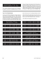
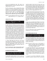
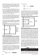
Refer to Fig. 28 to aid in understanding the relationship
of the LOW LIMIT WATER TEMP. (LLWT), HIGH LIMIT
WATER TEMP. (HLWT), CONTROL RANGE (CR) and
TARGET Temp.
To assure that the chilled liquid temperatures stay within
the CONTROL RANGE (CR), The micro will attempt to
control leaving chilled liquid temperature to an even tighter
temperature band than the low and high limits of the
CONTROL RANGE (CR). This temperature band is known
as the NEUTRAL ZONE. When chilled liquid is in the
NEUTRAL ZONE, the micro will only initiate loading/un-
loading pulses if temperature is rising or falling faster
than rate control limits internal to the micro.
As mentioned before, the user’s desired leaving water
temperature is known as the “TARGET” temperature and
is a temperature, midpoint in the CONTROL RANGE.
The “TARGET” is also midpoint in the NEUTRAL ZONE.
The NEUTRAL ZONE temperature band is not program-
mable but can be calculated as follows:
Example:
Neutral = Target +/- HLWT - LLWT
Zone
4
From the example:
Neutral
= 44°F +/-
46°F - 42°F
Zone
4
Neutral
= 44°F +/- 1°F
Zone
In the example above, with a CR = 42.0 to 46.0°F, the
“TARGET” temperature will be 44.0°F with a Neutral Zone
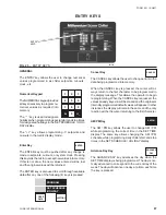
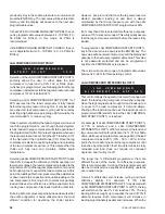
of 44.0°F +/- 1°F. Refer to Fig. 29 to aid in understanding
the relationship between the LOW LIMIT WATER TEMP.,
HIGH LIMIT WATER TEMP., “TARGET”, CONTROL
RANGE (CR), and NEUTRAL ZONE.
As mentioned previously, no loading or unloading will
occur in the NEUTRAL ZONE unless internal non-pro-
grammable rate control is exceeded. Limited loading will
occur in the temperature range between the top end of
the NEUTRAL ZONE and the HIGH LIMIT WATER TEMP.
(HLWT). Normal loading, dictated by internal timers will
occur above the CONTROL RANGE (CR). Limited un-
loading will occur when temperature falls between the
bottom of the NEUTRAL ZONE and the LOW LIMIT
WATER TEMP. (LLWT). Normal unloading, dictated by in-
ternal timers will occur below the CONTROL RANGE (CR).
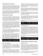
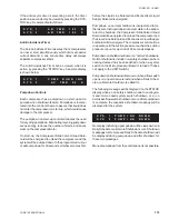
To program the CONTROL RANGE (CR), press the
CHILLED LIQUID TEMP. / RANGE key. For 3 seconds,
the display will show either that Local or Remote Water
Temp. Control is selected. The display will then automati-
cally scroll to the CONTROL RANGE (CR) and “TAR-
GET” temperature with the cursor stopping at the first
digit of the CONTROL RANGE (CR). Key in the Low Limit
of the CONTROL RANGE (CR) that is acceptable in the
system. See below:
Low Limit Water Temperature
The micro will accept a range of programmable values
from 10.0 - 70.0°F. To program setpoints below 38°F, Dip
Switch S1, Switch #1 on the Microprocessor Board must
FIG. 28 – CONTROL RANGE
FIG. 29 – NEUTRAL ZONE
C R
=
4 2 . 0
T O
4 6 . 0
° F
T A R G E T
=
4 4 . 0
° F
46.0°F
44.0°F
42.0°F
“TARGET”
TEMP.
CONTROL
RANGE
(CR)
HIGH LIMIT
WATER TEMP
LOW LIMIT
WATER TEMP
USER
ACCEPTABLE
LEAVING
CHILLED
LIQUID
OPERATING
RANGE
46.0°F
45.0°F
44.0°F
43.0°F
42.0°F
“TARGET”
TEMP.
CONTROL
RANGE
(CR)
HIGH LIMIT
WATER TEMP
LOW LIMIT
WATER TEMP
NEUTRAL ZONE
(No Loading/Unloading Occurs)
ÿ
ÿ
ÿ
ÿ
ÿ
ÿ
ÿ
ÿ
Summary of Contents for Millennium YCAS 216X
Page 11: ...FORM 201 10 NM1 11 YORK INTERNATIONAL YCAS 140 246 DIMENSIONS English LD01444 LD01446...
Page 13: ...FORM 201 10 NM1 13 YORK INTERNATIONAL YCAS 140 246 DIMENSIONS SI LD01440 LD01442...
Page 15: ...FORM 201 10 NM1 15 YORK INTERNATIONAL YCAS 216X 266X DIMENSIONS English LD01454 LD01454...
Page 17: ...FORM 201 10 NM1 17 YORK INTERNATIONAL YCAS 216X 266X DIMENSIONS SI LD01450 LD01448...
Page 33: ...FORM 201 10 NM1 33 YORK INTERNATIONAL 28514A FILTER DRYER LIQUID STOP VALVE...
Page 37: ...FORM 201 10 NM1 37 YORK INTERNATIONAL LD01285 FIG 3 SCREW CHILLER REFIGERANT FLOW DIAGRAM...
Page 59: ...FORM 201 10 NM1 59 YORK INTERNATIONAL FIG 11 CONTINUED LD01465 D...
Page 61: ...FORM 201 10 NM1 61 YORK INTERNATIONAL FIG 12 CONTINUED LD01458 D...
Page 69: ...FORM 201 10 NM1 69 YORK INTERNATIONAL FIG 16 CONTINUED LD01206 D...
Page 71: ...FORM 201 10 NM1 71 YORK INTERNATIONAL FIG 17 CONTINUED LD01202 D...

