


66
YORK INTERNATIONAL
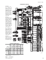
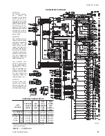
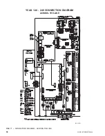
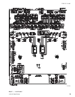
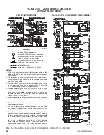
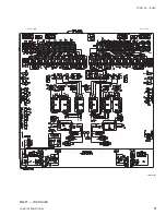
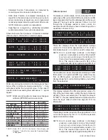
FIG. 15 – YCAS 216X - 266X ELEMENTARY DIAGRAM – WYE-DELTA START
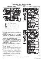
YCAS 216X - 266X WIRING DIAGRAM
WYE-DELTA START
POWER CIRCUIT OPTIONS
STANDARD DUAL COMPRESSOR POWER SUPPLIES
LD01201(D)
LD01201(D)
NOTES:
1. Field wiring to be in accordance with the current edition of the
National Electrical Code as well as all other applicable codes and
specifications.
2. Contacts must be suitable for switching 24VDC (gold contacts
recommended). Wiring shall not be run in the same conduit with
any line voltage wiring.
3. To cycle unit on and off automatically with contact shown, install
a cycling device in series with the flow switch (FLSW). See Note
2 for contact rating and and wiring specifications.
4. To stop unit (emergency stop) with contacts other than those
shown, install the stop contact between terminals 5 and 1. If a
stop device is not installed, a jumper must be connected be-
tween terminals 5 and 1. Device must have a minimum contact
rating of 100VA at 115 Volts A.C.
5. Alarm contacts are for annunciations alarm/unit malfunction. con-
tacts are rated at 115V, 100VA, resistive load only, and must be
suppressed at load by user.
6. See installation, operation and maintenance manuals when op-
tional equipment is used.
7. Use 2 KVA transformer inoptional transformer kit unless there
are optional oil separator sump heaters which necessitates us-
ing 3 KVA transformers.
8. Power factor correction capacitors may be installed on the chiller
electrical system (as shown) as a field supplied option. The power
factor correction capacitors must be installed in accordance with
the National Electrical Code Article 460 as well as all other appli-
cable codes and specifications. Power factor correction capaci-
tors may be installed only on the line side of the chiller electrical
system with correction not to exceed a PF of more than 0.96. A
separate disconnect switch, over current protection and dis-
charge resistors are required.
LEGEND
Transient Voltage Suppression
Terminal Block for Customer Connections
Terminal Block for Customer Low Voltage
(Class 2) Connections. See Note 2
Terminal Block for YORK Connections Only
Wiring and Components by YORK
Optional Equipment
Wiring and/or Components by Others
T S
Summary of Contents for Millennium YCAS 216X
Page 11: ...FORM 201 10 NM1 11 YORK INTERNATIONAL YCAS 140 246 DIMENSIONS English LD01444 LD01446...
Page 13: ...FORM 201 10 NM1 13 YORK INTERNATIONAL YCAS 140 246 DIMENSIONS SI LD01440 LD01442...
Page 15: ...FORM 201 10 NM1 15 YORK INTERNATIONAL YCAS 216X 266X DIMENSIONS English LD01454 LD01454...
Page 17: ...FORM 201 10 NM1 17 YORK INTERNATIONAL YCAS 216X 266X DIMENSIONS SI LD01450 LD01448...
Page 33: ...FORM 201 10 NM1 33 YORK INTERNATIONAL 28514A FILTER DRYER LIQUID STOP VALVE...
Page 37: ...FORM 201 10 NM1 37 YORK INTERNATIONAL LD01285 FIG 3 SCREW CHILLER REFIGERANT FLOW DIAGRAM...
Page 59: ...FORM 201 10 NM1 59 YORK INTERNATIONAL FIG 11 CONTINUED LD01465 D...
Page 61: ...FORM 201 10 NM1 61 YORK INTERNATIONAL FIG 12 CONTINUED LD01458 D...
Page 69: ...FORM 201 10 NM1 69 YORK INTERNATIONAL FIG 16 CONTINUED LD01206 D...
Page 71: ...FORM 201 10 NM1 71 YORK INTERNATIONAL FIG 17 CONTINUED LD01202 D...


