134
YORK INTERNATIONAL
PANEL CHECKS
(Power On – Both System Switches “OFF”)
q
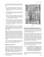
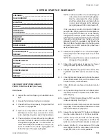
1. Apply 3 phase power and verify its value (See
Fig. 20).
q
2. Apply 115VAC and verify its value on the termi-
nal block in the lower left of the Power Panel.
Make the measurement between terminals 5 and
2 of TB1 (See Fig. 20.). The voltage should be
/- 10%.
q
3. Assure the heaters on each compressor are on.
Allow the compressor heaters to remain on a mini-
mum of 24 hours before startup. This is impor-
tant to assure that no refrigerant is in the com-
pressor oil at start-up!
q
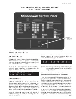
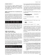
4. Program the dip switches on the microprocessor
board for the desired operating requirements. See
Page 80. OPEN = Left side of switch pushed down.
CLOSED = Right side of switch pushed down.
SW#
OPEN
CLOSED
1
Water
Brine
2
Std Amb
Low Amb
3
Local
Remote
4
N/A
N/A
5
English
SI (Metric)
6
ACL Start
W-D Start
7
M Lead/Lag
A Lead/Lag
8
R- 1 34a
R-22
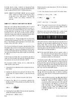
Verify the selections by pressing the OPTIONS
Key on the control panel. Check them off.
CAUTION: Damage to the chiller could result if
switches are improperly programmed.
q
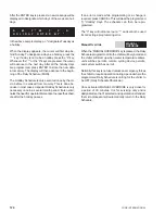
5. Program the required twenty-two operating val-
ues into the micro for cut-outs, safeties, etc. and
record them in the chart below. See Page 88.
If Default Values are desired for programming con-
venience, press the PROGRAM key, 6140, and
ENTER. This loads default values. Record these
values in the chart below.
PROGRAMMED VALUES
Refrigerant Type = _____________________________
Dischg Press Cut-out = _______________ PSIG (kPa)
Low Amb Cut-out = ______________________ °F (°C)
High Amb Cut-out = ______________________ °F (°C)
Disch Press Unld = ___________________ PSIG (kPa)
Avg Current Unld = ________________________ %FLA
Anti Recycle Time = _______________________ Secs
LWT Cut-out = ___________________________ °F (°C)
Suction Press Cut-out = _______________ PSIG (kPa)
Lag Cmpr Start Point = ____________________ %FLA
Lag Compr Diff Off = ______________________ %FLA
Fan Dsch Press Setpt = _______________ PSIG (kPa)
Fan On/Off Press Diff = _______________ PSIG (kPa)
Sys 1 Curr = 100 %FLA = _________________ AMPS
Sys 2 Curr= 100 %FLA = __________________ AMPS
Liq Inj Temp Limit = ______________________ °F (°C)
Sys 1 Cond Tmp = ________________ °F (°C) = 100%
Sys 2 Cond Tmp = ________________ °F (°C) = 100%
Com Mode = ISN ___________ or RCC ___________
Load Share = SV% __________ or %FLA __________
Econ Valve On Point = __________________________
Econ Valve Off Point = __________________________
q
6. Program the Chilled Liquid Temp/Range and
record:
CR = ________ to _________ °F (°C)
Target = ____________ °F (°C)
Keep in mind that the Target temperature dis-
played by the micro should equal the desired leav-
ing water temperature.
q
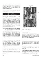
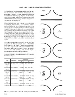
7. Assure that the CLK jumper J18 on the Micropro-
cessor Board is in the ON position (Top 2 pins).
q
8. Set the Time and Date.
q
9. Program the Daily Schedule start and stop times.
INITIAL START-UP
After the control panel has been programmed and the
compressor heater has been on for 24 hours prior to
start-up, the chiller may be placed into operation.
q
1. Place the System Switches on the Microproces-
sor Board to the ON position.
Summary of Contents for Millennium YCAS 216X
Page 11: ...FORM 201 10 NM1 11 YORK INTERNATIONAL YCAS 140 246 DIMENSIONS English LD01444 LD01446...
Page 13: ...FORM 201 10 NM1 13 YORK INTERNATIONAL YCAS 140 246 DIMENSIONS SI LD01440 LD01442...
Page 15: ...FORM 201 10 NM1 15 YORK INTERNATIONAL YCAS 216X 266X DIMENSIONS English LD01454 LD01454...
Page 17: ...FORM 201 10 NM1 17 YORK INTERNATIONAL YCAS 216X 266X DIMENSIONS SI LD01450 LD01448...
Page 33: ...FORM 201 10 NM1 33 YORK INTERNATIONAL 28514A FILTER DRYER LIQUID STOP VALVE...
Page 37: ...FORM 201 10 NM1 37 YORK INTERNATIONAL LD01285 FIG 3 SCREW CHILLER REFIGERANT FLOW DIAGRAM...
Page 59: ...FORM 201 10 NM1 59 YORK INTERNATIONAL FIG 11 CONTINUED LD01465 D...
Page 61: ...FORM 201 10 NM1 61 YORK INTERNATIONAL FIG 12 CONTINUED LD01458 D...
Page 69: ...FORM 201 10 NM1 69 YORK INTERNATIONAL FIG 16 CONTINUED LD01206 D...
Page 71: ...FORM 201 10 NM1 71 YORK INTERNATIONAL FIG 17 CONTINUED LD01202 D...

