York MILLENIUM YCAS Series Installation Operation & Maintenance Download Page 97

97

YORK INTERNATIONAL

FORM 201.18-NM6

29023A

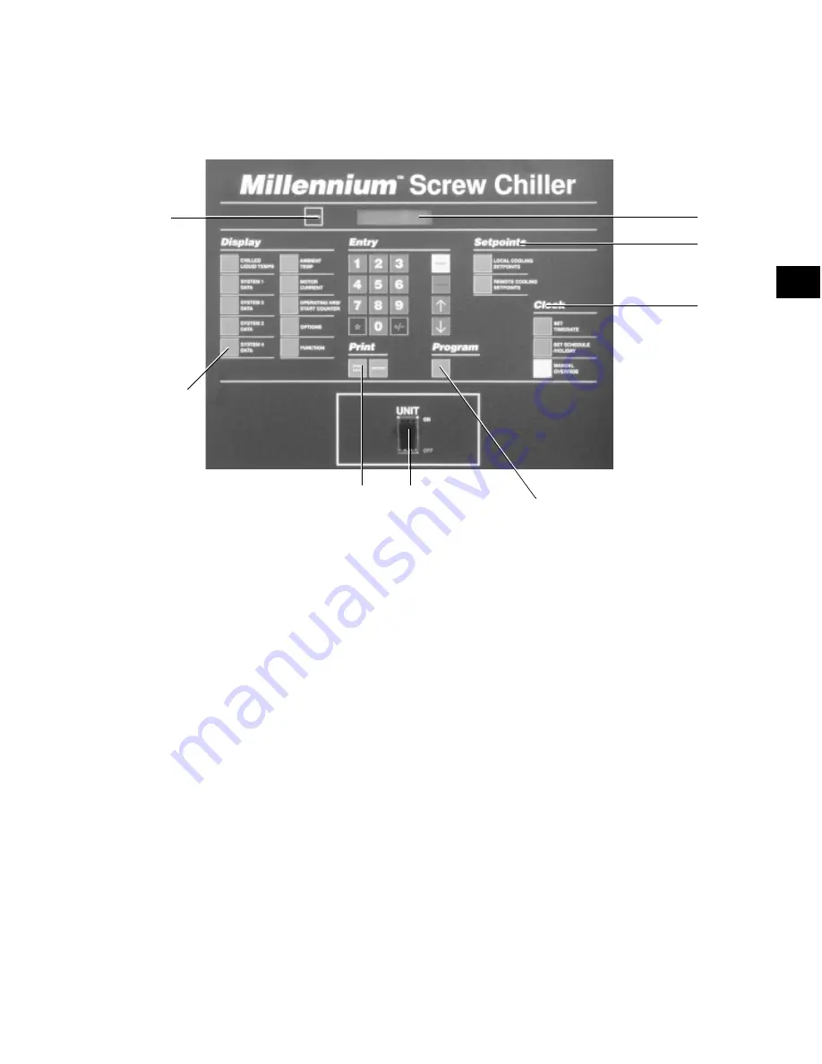
CHILLER CONTROL PANEL

PROGRAMMING AND DATA ACCESS KEYS

CLOCK

SETPOINTS

PROGRAM &
SETUP KEY

ON / OFF

DISPLAY
INFORMATION KEYS

STATUS

PRINT

DISPLAY AND STATUS INFORMATION KEYS

Status Key - see Section 2
This key provides a display of the current operational
and/or fault status of the chiller or individual refriger-
ant systems.

Display Keys - see Section 3
Each key provides a real time display of commonly re-
quired information about the chiller and individual sys-
tem operating conditions and settings.

Print Keys - see Section 4
These keys allow control panel display or remote print-
out of both current real-time operating and programmed
data as well as fault history data from recent safety shut-
downs.

ON / OFF ROCKER SWITCH

This switch shuts down the entire chiller when placed
in the OFF position. The switch must be ON for the
chiller to operate.

PROGRAM & SETUP KEYS

Entry Keys - see Section 5
The numeric and associated keys are used for entering
data required for programming the chiller. The ENTER
and 

!#

!#

!#

!#

!#

keys are also used for scrolling through infor-

mation available after pressing certain keys.

Setpoints Keys - see Section 6
These keys are used for display and programming of
the local and remote offset chilled liquid temperature
setpoints.

Clock Keys - see Section 7
These keys are used for display and programming of
the clock and operating schedule for the chiller.

Program Key - see Section 8
This key is used for display and programming of the
chiller operational settings and limits.

DISPLAY

8

Summary of Contents for MILLENIUM YCAS Series

Page 1: ...MILLENNIUM AIR COOLED SCREW LIQUID CHILLERS New Release Form 201 18 NM6 800 MILLENNIUM YCAS AIR COOLED SCREW LIQUID CHILLERS YCAS0283 through YCAS0343 YCAS 2 SYSTEM EPROM 031 01798 001 STANDARD BRINE...

Page 2: ...r Connection Standard 21 Single Point Power Connection with Individual Circuit Protection 21 Single Point Power Connection with Combined Circuit Protection 21 Single Point Power Connection without Cir...

Page 3: ...ycol Correction Factors 43 TemperatureandFlows 44 Physical Data SI Units 45 Operating Limitations Sound Power Data 46 Electrical Data 48 Multiple Point Power Supply Connection 48 Optional Single Point...

Page 4: ...rator Heater Control 107 1 18 Pumpdown LLSV Control 107 1 19 Alarms 107 1 20 Run Status Chiller 108 1 21 Lead Lag Compressor Selection 108 2 STATUSKEY GENERALSTATUSMESSAGESANDFAULTWARNINGS 109 2 1 Gen...

Page 5: ...2 Program Key User Programmable Values 137 8 3 Programming Default Values 141 8 4 4 Condenser Fan Control 142 SECTION 9 MAINTENANCE 146 General Requirements 146 Daily Maintenance 146 Scheduled Mainten...

Page 6: ...hat the failure has occurred within the warranty period and that the unit has been operated within the designed parameters specified All warranty claims must specify the unit model serial number order...

Page 7: ...suitable for purposes other than those specified in these instructions Any use of the equipment other than its intended use or operation of the equipment contrary to the relevant procedures may resul...

Page 8: ...oves and safety glasses are however recommended when working on the unit The build up of refrigerant vapor from a leak for ex ample does pose a risk of asphyxiation in confined or enclosed spaces and...

Page 9: ...that R 22 does not represent a carcinogenic hazard to humans Occupational Recommended limit 1000 ppm v v 8 hr TWA 1250 ppm v v 12 hr TWA Exposure Limits Stability Unstable Conditions to Avoid Use in p...

Page 10: ...highly recommended Section 4 PHYSICAL DATA Appearance Clear liquid gray to yellow or light brown tint Boiling Point 650 F Vapor Pressure 0 01 mmHg 20 C Specific Gravity water 1 0 94 0 97 Volatiles Pe...

Page 11: ...atory Protection Use in well ventilated area Ventilation Local exhaust Protective Gloves Strongly recommended especially for prolonged exposure Eye Face Protection Goggles Firefighters should use NIOS...

Page 12: ...posed power wiring is be routed through liquid tight non metallic conduit General Description The Air Cooled Screw Chiller utilizes many compo nents which are the same or nearly the same as a stan dar...

Page 13: ...nal oil separator The pres surized oil is then cooled in the condenser coils and piped back to the compressor for lubrication The com pressor design working pressure is 31 bar 450 PSIG Each chiller re...

Page 14: ...e liquid line solenoid after pumpdown The economizer operation is controlled by the econo mizer solenoid valve This valve is controlled by the microprocessor The valve will remain off for the first 3...

Page 15: ...le smooth loading Automatic spring return of the slide valve to the mini mum load position will ensure compressor starting at minimum motor load Power and Control Panel All controls and motor starting...

Page 16: ...t opens This occurs because the MP and HPCO contacts are in series with the motor contactor Whenever either of these devices are open the contactor de energizes and the motor shuts down Since the micr...

Page 17: ...mal protection The sensor resistance stays rela tively constant at 1k until a temperature of 130 C 266 F is sensed The sensor experiences a rapid rise in resistance beyond this temperature Whenever th...

Page 18: ...50 HZ MODEL VOLT CHILLER 100 NO MOTOR PROTECTOR NO CODE NAMEPLATE FLA LEADS MP OL RLA OF PER VALUE SYS PHASE SET DIP SWITCH SETTINGS ON MP 1 INDICATED ON 128 64 32 16 8 4 2 1 0283 50 68 73 2 92 0 1 0...

Page 19: ...50 HZ MODEL VOLT CHILLER 100 NO MOTOR PROTECTOR NO CODE NAMEPLATE FLA LEADS MP OL RLA OF PER VALUE SYS PHASE SET DIP SWITCH SETTINGS ON MP 1 INDICATED ON 128 64 32 16 8 4 2 1 0283 50 68 73 2 92 0 1 0...

Page 20: ...enabled by the microprocessor from Relay Out put Board 1 Terminal 8 SYS 1 or Relay Output Board 2 Terminal 6 SYS 2 The 1TR SYS 1 or 2TR SYS 2 contacts open de energizing 1S SYS 1 or 2S SYS 2 1M SYS 1...

Page 21: ...uminum fins cop per tubes and galvanized steel supports for generally adequate corrosion resistance However these materi als are not adequate for all environments Entry Used to confirm Set Point chang...

Page 22: ...F with 1 NPT IPS connection for upright mounting in horizontal pipe A flow switch must be field installed with each unit Star Delta Compressor Motor Starter Provides approximately 65 reduced inrush c...

Page 23: ...rew High Efficiency R 22 Design Series F Engineering Change or PIN Level BASIC PART NUMBER 1 2 3 4 5 6 7 8 9 10 11 12 13 14 15 BASE PRODUCT TYPE NOMINAL CAPACITY UNIT DESIGNATOR REFRIGERANT VOLTAGE ST...

Page 24: ...n Seismic Neoprene Pads 38 39 40 41 42 43 44 45 46 47 48 49 50 51 52 53 54 3 X 1 D C 2 W B 3 V P 4 S X 5 M 6 A 7 S 8 F E T X I B P L R H X S 1 S N UNIT NOMENCLATURE NAMEPLATE ENGINEERING DATA OPTIONS...

Page 25: ...rson on site It is recommended that the unit is periodically in spected during storage 3 INSPECTION Remove any transit packing and inspect the unit to en sure that all components have been delivered a...

Page 26: ...26 YORK INTERNATIONAL UNIT RIGGING Handling and Storage 88 2250mm CORRECT WRONG LD03514 FIG 3 UNIT RIGGING CORRECT WRONG LD03515 FIG 4 LIFTING LUGS...

Page 27: ...s of suitable strength The channels should be spaced at the same centres as the vibration mounting holes in the unit base frame and must be at least 120 mm 4 3 4 wide at the contact points This will a...

Page 28: ...provided on page 83 Installation SHIPPING BRACES The chiller s modular design does not require shipping braces PIPEWORK CONNECTION General Requirements The following piping recommendations are intend...

Page 29: ...d to ensure liquid is circu lated when the ambient temperature approaches freez ing point Insulation should also be installed around the cooler nozzles Heater tape of 21 watts per meter under the insu...

Page 30: ...recautions should be taken to ensure that the outlet of relief valves vent pipe remain clear of obstructions at all times DUCTWORK CONNECTION General Requirements The following ductwork recommendation...

Page 31: ...all overcurrent protection devices between the supply conductors and the power supply terminals on the unit To ensure that no eddy currents are set up in the power panel the cables forming each 3 phas...

Page 32: ...d 38 close to start the chilled liquid pump This contact can be used as a master start stop for the pump in conjunc tion with the daily start stop schedule Run Contact Terminals 29 and 30 Figs 12 and...

Page 33: ...33 YORK INTERNATIONAL FORM 201 18 NM6 POWER AND CONTROL PANEL LAYOUTS WYE DELTA TYPICAL FIG 8 POWER PANEL SECTION 00263VIP 4...

Page 34: ...34 YORK INTERNATIONAL FIG 9 OPTION PANEL SECTION OPTIONS PANEL LAYOUT TYPICAL 00246VIP Installation...

Page 35: ...OGIC SECTION LAYOUT LOGIC SECTION LAYOUT 00247VIP ITEM 1 2 3 4 5 6 7 8 9 DESCRIPTION Microprocessor Board Back of Keypad Back of Display I O Expansion Board 1 Power Supply Board Relay Output Board 1 R...

Page 36: ...36 YORK INTERNATIONAL FIG 11 LOGIC SECTION LAYOUT WITH CONTROL PANEL LAYOUT LOGIC SECTION LAYOUT WITH CONTROL PANEL LAYOUT 00248VIP Installation...

Page 37: ...EMERGENCY STOPS TERMINALS 13 19 TERMINALS 23 38 4 Print Temperature PWM Current PWM Flow Switch System No 1 Run System No 2 Run 13 13 13 13 13 14 15 16 17 18 19 23 24 25 26 27 28 29 30 System No 1 Al...

Page 38: ...TOMER CONNECTIONS CUSTOMER CONNECTIONS Installation TRANSFORMERS POWER SUPPLY BOARD CIRCUIT BREAKERS RELAY BOARDS I O EXPANSION BOARD CUSTOMER CONNECTIONS Flow Switch Alarm Run etc MICROPROCESSOR CIRC...

Page 39: ...ormer is mounted in the op tions panel It is important to check that the correct pri mary tapping has been used With the supply to the unit isolated remove the lid to the transformer box COMMISSIONING...

Page 40: ...r outlet and wired into the control panel correctly using shielded cable There should be a straight run of at least 5 pipe diam eters on either side of the flow switch The flow switch should be connec...

Page 41: ...r and be replaced by a solid column of liquid Fan Rotation As discharge pressure rises the condenser fans oper ate in stages to control the pressure Verify that the fan operation is correct for the ty...

Page 42: ...operations are fully automatic After an initial period at minimum capacity on the lead compressor the control system will adjust the unit load depending on the chilled liquid tempera ture and rate of...

Page 43: ...cause additional pressure drop When using glycol solutions pressure drops are higher than with water see correction factors to be applied when using glycol solutions Special care must be taken not to...

Page 44: ...3 The evaporator is protected against freezing to 28 8 C 20 F with an electric heater as standard TEMPERATURE AND FLOWS SI UNITS Technical Data Excessive flow above the max l s will damage the evapora...

Page 45: ...r Coil Face Area m2 7 8 7 8 7 8 7 8 Number of Rows 3 3 3 3 Fins per Meter 512 512 512 512 Condenser Fans Number Ckt 1 Ckt 2 3 3 3 3 3 3 3 3 Number Ckt 3 Ckt 4 Standard Fans Fan Motor HP kW 2 1 6 2 1 6...

Page 46: ...CE C 3 10 WATER SIDE PRESSURE BAR 10 REFRIGERANT SIDE PRESSURE BAR 20 MINIMUM PRIMARY COOLER FLOW MODEL WATER VOLUME LITERS SECOND YCAS LITERS MIN MAX 0283EC 2570 7 1 37 9 0303EC 2748 7 7 37 9 0323EC...

Page 47: ...47 YORK INTERNATIONAL FORM 201 18 NM6 7 This page intentionally left blank...

Page 48: ...protection Field Power Wiring connections to factory provided Non Fused Disconnect Switches Opt or Terminal Blocks Opt in the Option Box Model Volts MRA1 Min NF Protection13 Factory Provided Lugs Wir...

Page 49: ...S MCA Disc Sw 2 9 Min 3 5 Max 4 6 Std Terminal Optional NF Optional RLA Y LRA X LRA Qty FLA LRA Block Disc Sw Circuit Breaker Ea Ea 0283 380 99 100 125 150 18 2 14 250 14 250 68 175 523 3 4 4 17 1 030...

Page 50: ...d Provided Power Supply Factory Provided Lugs Wire Range 7 YCAS MRA1 Min NF Over Current Protection13 Standard Optional NF MCA Disc Sw 2 9 Min 3 5 Max 4 6 Terminal Block Disc Switch 0283 380 197 200 2...

Page 51: ...ata Fan Data11 12 YCAS RLA Y LRA X LRA Qty FLA LRA RLA Y LRA X LRA Qty FLA LRA Ea Ea Ea Ea 0283 380 68 0 175 523 3 4 0 17 1 68 0 175 0 523 3 4 4 17 1 0303 380 71 0 175 523 3 4 0 17 1 71 0 175 0 523 3...

Page 52: ...LD06177 OPTIONAL SINGLE POINT POWER SUPPLY CONNECTION One field provided power supply circuit to the unit with field supplied circuit protection Field connections to factory provided Non Fused Disconn...

Page 53: ...Compressor Data Fan Data11 12 YCAS RLA Y LRA X LRA Qty FLA LRA RLA Y LRA X LRA Qty FLA LRA Ea Ea Ea Ea 0283 380 68 N A 523 3 4 4 17 1 68 N A 523 3 4 4 17 1 0303 380 71 N A 523 3 4 4 17 1 71 N A 523 3...

Page 54: ...protection Field connections to factory provided Circuit Breaker in the Options Panel Factory connections to Terminal Blocks in each of the two Power Panels FIELD SUPPLIED WIRING SYSTEM 1 SYSTEM 2 Mo...

Page 55: ...MUM kW AND AMPERAGE VALUES FOR DXST COMPRESSORS COMPRESSOR MODEL AND VOLTAGE CODE DXS45LA MOTOR CODE A DXS36LA MOTOR CODE A DXS24LA MOTOR CODE TBD B5N B5E B6N B6E A5N A5E A6N A6E C5N C5E C6N C6E VOLTA...

Page 56: ...pacity and job requirements using N E C wire sizing information The above recommendations are based on the National Electric Code and using copper connectors only Field wiring must also comply with lo...

Page 57: ...contacts shown install a cycling device in series with the flow switch See Note 2 for contact rating and wiring specifi cations 4 To stop unit Emergency Stop with contacts other than those shown insta...

Page 58: ...58 YORK INTERNATIONAL WIRING DIAGRAM ACROSS THE LINE START FIG 17 WIRING DIAGRAM ACROSS THE LINE START Technical Data LD06015...

Page 59: ...59 YORK INTERNATIONAL FORM 201 18 NM6 7 This page intentionally left blank...

Page 60: ...60 YORK INTERNATIONAL FIG 18 ELEMENTARY DIAGRAM ACROSS THE LINE START ELEMENTARY DIAGRAM Technical Data...

Page 61: ...re lays wired in series with the flow switch for start stop in the Alarm cir cuitry or pilot relays for pump starters wired through motor contactor auxiliary contact must be suppressed with YORK P N 0...

Page 62: ...witching 24VDC Gold contacts recommended Wiring shall NOT run in the same conduit with any line voltage Class 1 wiring 3 To cycle unit ON and OFF automatically with contacts shown install a cycling de...

Page 63: ...63 YORK INTERNATIONAL FORM 201 18 NM6 7 WIRING DIAGRAM WYE DELTA START LD06015...

Page 64: ...64 YORK INTERNATIONAL FIG 20 ELEMENTARY DIAGRAM WYE DELTA START Technical Data ELEMENTARY DIAGRAM Technical Data ELEMENTARY DIAGRAM Technical Data...

Page 65: ...e lays wired in series with the flow switch for start stop in the Alarm cir cuitry or pilot relays for pump starters wired through motor contactor auxiliary contact must be suppressed with YORK P N 03...

Page 66: ...66 YORK INTERNATIONAL Technical Data LD06017 PANEL COMPONENT LOCATIONS FIG 21A CONTROL PANEL COMPONENT LOCATIONS...

Page 67: ...the System 1 and System 2 Power Panels are located on the left and right side respectively of the Control Panel They have been shown separately from the Control Panel in order to make the drawings lar...

Page 68: ...68 YORK INTERNATIONAL Technical Data LEGEND 0283 0343 LD06179...

Page 69: ...69 YORK INTERNATIONAL FORM 201 18 NM6 7 LD05957...

Page 70: ...70 YORK INTERNATIONAL Technical Data CONNECTION DIAGRAM SYSTEM WIRING LD06019...

Page 71: ...71 YORK INTERNATIONAL FORM 201 18 NM6 7 COMPRESSOR TERMINAL BOX LD06020...

Page 72: ...ential performance degradation Access to the unit control center assumes the unit is no higher than on spring isolators Recommended minimum clearances Side to wall 2m rear to wall 2m control panel end...

Page 73: ...C POWER POWER CONTROL OPTIONS PANEL FOR SYS 2 POWER ELEMENTS FOR SYS 1 POWER ELEMENTS DISTRIBUTION ORIGIN VIEW D D MOUNTING 16 DIA HOLES TYP APPROX OPERATING WEIGHT KG A B C D E F LD04479 LD05207 CENT...

Page 74: ...2 m 2 m 2 m TECHNICAL DATA CLEARANCES Notes 1 No obstructions allowed above the unit 2 Only one adjacent wall may be higher than the unit 3 Adjacent units should be 10 feet 3 meters apart LD05903 FIG...

Page 75: ...NTS ORIGIN VIEW D D MOUNTING 5 8 DIA HOLES TYP A B C D E F Aluminum Fin and Black Fin Condenser Coils WEIGHT DISTRIBUTION AND ISOLATOR MOUNTING POSITIONS 7 LD04475 ALUMINUM BLACK FIN COIL WEIGHT DISTR...

Page 76: ...27 1500 680 4 1 06 26 9 Orange CP 2 28 1800 816 4 1 02 25 9 Green CP 2 31 2200 997 9 0 83 21 0 Gray CP 2 32 2600 1179 3 0 74 18 7 White CP 2 35 3000 1360 8 0 70 17 7 Gold FIG 23 CP 2 XX ISOLATOR DETA...

Page 77: ...ns mm TYPE CODE lbs kg R RD R 3 BLACK 250 113 5 0 25 0 50 OR RED 525 238 3 6 3 12 7 RD 3 GREEN 750 340 5 GRAY 1100 499 4 R 4 BLACK 1500 681 0 0 25 0 50 OR RED 2250 1021 5 6 3 12 7 RD 4 GREEN 3000 1362...

Page 78: ...MR 1 552 1900 861 8 2 51 AWMR 1 553 2200 997 9 2 51 AWMR 2 531 2552 1157 6 2 51 AWMR 2 532 3000 1360 8 2 51 A B C D E F G H I J K L M N X AWMR 1 10 1 2 6 3 5 8 3 4 3 1 2 1 3 4 1 2 9 5 8 8 1 2 4 1 4 10...

Page 79: ...13 16 Y X C FOR SYS 1 CONTROL OPTIONS PANEL POWER ELEMENTS FOR SYS 2 POWER POWER POWER ELEMENTS ORIGIN VIEW D D MOUNTING 5 8 DIA HOLES TYP A B C D E F LD04475 COPPER FIN COIL WEIGHT DISTRIBUTION BY M...

Page 80: ...R CP 2 26 1200 544 3 1 17 29 7 Purple CP 2 27 1500 680 4 1 06 26 9 Orange CP 2 28 1800 816 4 1 02 25 9 Green CP 2 31 2200 997 9 0 83 21 0 Gray CP 2 32 2600 1179 3 0 74 18 7 White CP 2 35 3000 1360 8 0...

Page 81: ...ING IS PREFERRED Type R or RD mountings are may be used without bolting under machines having no lateral or severe vertical motion NEW DESIGN FOR TYPE RD 4 NEOPRENE MOUNTINGS TYPE RD 3 LD04033 29518A...

Page 82: ...C 5 8 DIMENSIONS In 60 HERTZ COPPER FINS SEISMIC ISOLATOR SELECTIONS VMC MODEL AWMR SEE TABLE BELOW YCAS A B C D E F 0283 1 551 1 532 1 530 1 532 1 532 1 531 0303 1 551 1 532 1 530 1 532 1 532 1 531 0...

Page 83: ...eight of the isolator To use the isolator as blocking for the equipment insert a 1 4 shim between the upper load plate and vertical uprights Lower the equipment on the blocking or shimmed isolators 5...

Page 84: ...he cooler shell Low pressure vapor enters the compressor where pres sure and superheat are increased High pressure vapor is passed through the oil separator where compressor oil is removed and recircu...

Page 85: ...85 YORK INTERNATIONAL FORM 201 18 NM6 PROCESS AND INSTRUMENTATION DIAGRAM LD03486 FIG 28 PROCESS AND INSTRUMENTATION DIAGRAM Added to some models 7...

Page 86: ...BDT DISCHARGE TEMPERATURE BOP OIL PRESSURE BOT OIL TEMPERATURE BSP SUCTION PRESSURE CCCV COMPRESSOR CAPACITY CONTROL VALVE ECH CRANK CASE HEATER EEH EVAPORATOR HEATER SHPI HIGH PRESSURE CUT OUT STS SU...

Page 87: ...EDHOLE OIL HEATER ECONOMIZER GAS IN DISCHARGE CASE OILINLET FROMCONDENSER CODINGCOIL DISCHARGE GAS OUT OILFILTER BLEED EVACUATION POINT OILFILTER COVER PLATE CAPACITY CONTROL SOLENOID CAPACITY CONTROL...

Page 88: ...88 YORK INTERNATIONAL COMPRESSOR COMPONENTS CONT D FIG 31 COMPRESSOR COMPONENTS LD03669 Technical Data...

Page 89: ...89 YORK INTERNATIONAL FORM 201 18 NM6 COMPRESSOR COMPONENTS CONT D FIG 32 COMPRESSOR COMPONENTS LD03670 7...

Page 90: ...90 YORK INTERNATIONAL COMPRESSOR COMPONENTS CONT D FIG 33 COMPRESSOR COMPONENTS LD06232 Technical Data LD06231...

Page 91: ...T BEARING 22 BEARING CLAMP NUT 23 BEARING SPACER SLEEVE 24 BEARING PRELOAD SPRING 25 O RING 26 BEARING BORE PLUG 27 DISCHARGE COVER 28 BEARING BORE PLUG 29 BEARING PRELOAD SPRING 30 BEARING SPACER SLE...

Page 92: ...SSOR COMPONENTS CONT D FIG 35 COMPRESSOR COMPONENTS O RING MOTOR ROTOR MALE ROTOR LOCKING KEY MALE ROTOR FEMALE ROTOR O RING RELIEF VALVE ECONOMIZER PLUG SUPPORT RINGS LD03672 SLIDE VALVE RETURN SPRIN...

Page 93: ...d completely in their respective wells and are coated with heat conductive compound 14 Assure that evaporator TXV bulbs are strapped onto the suction lines at 4 or 8 o clock posi tions 15 Assure that...

Page 94: ...is in the ON position Top 2 pins 8 Set the Time and Date 9 Program the Daily Schedule start and stop times Panel Checks Power ON Both System Switches OFF 1 Apply 3 phase power and verify its value Se...

Page 95: ...laced into operation 1 Place the System Switches on the Micropro cessor Board to the ON position 2 The compressor will start and a flow of refrig erant will be noted in the sight glass After sev eral...

Page 96: ...on temperature suction pres sure suction pressure converted to temperature and superheat of each system below Normally the thermal expansion valve need not be ad justed in the field If however adjustm...

Page 97: ...programmed data as well as fault history data from recent safety shut downs ON OFF ROCKER SWITCH This switch shuts down the entire chiller when placed in the OFF position The switch must be ON for the...

Page 98: ...ividual refrigerant systems are provided on the Mi croprocessor Board s External interface is available for control of the chiller via a YORK ISN System or YORK Remote Control Center In addition EMS B...

Page 99: ...period regardless of the time involved The battery is a 10 year lithium type but life will depend upon whether the Real Time Clock s internal clock cir cuit is energized With the clock OFF a rated li...

Page 100: ...e System 1 for control system circuitry servicing Specifically the 115VAC feed to Relay Output Board 1 which energizes contactors and solenoids CB2 allows removal of control power from respec tive Sys...

Page 101: ...or dip switches These switches are set at the fac tory according to motor specifications The module also provides phase rotation protection to assure the screw compressor does not rotate backwards A s...

Page 102: ...102 YORK INTERNATIONAL FIG 36 MOTOR PROTECTION MODULE SIDE VIEW 29119A 29121A TOP VIEW TOP VIEW SIDE VIEW 29121A 29120A DISPLAY SWITCH PUSHED TO LEFT INDICATES ON ON Micro Panel Contents...

Page 103: ...control panel The duration of the contact clo sure will determine the amount of adjustment Gener ally this input is used for purposes of demand limit and operates as follows Closing the input contact...

Page 104: ...Reset Temp 4 sec 1 sec X 22 C 10 sec Reset Temp 66 C sec 10 sec 6 C 12 F To determine the new setpoint add the reset to the setpoint programmed into memory In the example above if the programmed setpo...

Page 105: ...k Enable Disable Jump Contact Real Time Clock and Battery Backup I C Microprocessor I C label shows version NOTE Dimple is positioned at top edge Dip Switch Set 8 switches System Switches S2 System 1...

Page 106: ...EL LOGIC SECTION FIG 38 LOGIC SECTION LAYOUT ITEM 1 2 3 4 5 6 7 DESCRIPTION Microprocessor Board Back of Keypad I O Expansion Board 1 Power Supply Board Relay Output Board 1 Relay Output Board 2 Flow...

Page 107: ...heater will turn on and stay on for 5 minutes After 5 minutes has elapsed the heater will shut off if the discharge temperature rises above 66 C 150 F and will turn on when the discharge tem perature...

Page 108: ...s is not available 1 21 LEAD LAG COMPRESSOR SELECTION The chiller may be set up for AUTO or MANUAL Lead Lag This is accomplished by programming the option un der the Program Key Details for programmin...

Page 109: ...ges These messages are described in detail below with ex amples of each display In each example is used as applicable to represent the system number where mes sages apply to individual systems 2 2 GEN...

Page 110: ...ding Requirement This message indicates that chilled liquid temperature is below the point where the microprocessor will bring the lead system on and or that the loading sequence has not loaded the ch...

Page 111: ...age 103 Suction Temperature Limiting The Suction Temperature Limiting message applies only when the chiller is set for Water Cooling Mode see page 119 The message indicates that saturated suction tem...

Page 112: ...ng demand requires addi tional cooling A reset hysteresis is built into each safety so repetitive faulting and clearing will not occur in a short time period Continuous monitoring by the microprocesso...

Page 113: ...R 22 models as long as the compressor continues to run sor is running Any external cycling devices fitted by the customer are connected in series with the flow switch es YCAS 2 System chillers have a...

Page 114: ...h Oil Differential Safety since no flow will cause the differential through the oil piping to drop to zero EXAMPLE For ambients above 10 C 50 F the Low Oil Differ ential Safety is activated after 1 mi...

Page 115: ...elow 10 of the cut out initially programmed and must be greater than C O Programmed C O X Time 1 33 3 This transient cutout value increases with time until after 30 seconds it equals the programmed cu...

Page 116: ...control power from the micro panel after the motor sensors have sufficient time to cool Details relating to operation of the Motor Protec tion Module can be found on page 16 The External Motor Overloa...

Page 117: ...m monly required data about the operation of the chiller This is particularly useful during commissioning moni toring the operation of the chiller diagnosing potential future problems and service trou...

Page 118: ...s are as follows where is the appropriate system number The Cooler Inlet Temp display will only appear if the chiller is selected for R 407c Temperatures and pressures are either measured directly by...

Page 119: ...ow Chilled Liq uid Cut Out can be programmed from 13 to 2 C 8 to 36 F and the Suction Pressure Cut Out programmed from 1 to 5 bar 20 to 70 PSIG for R 22 models and 0 3 to 5 bar 5 to 70 PSIG for R 407c...

Page 120: ...refrigerant R 407C Incorrect selection of this switch may cause serious damage to the chiller Closed The R 22 Mode MUST be selected for models using refrigerant type R 22 Incorrect selection of this s...

Page 121: ...Spare Spare 3 8 FUNCTION KEY Pressing the Function key only displays the same mes sage as pressing the Status key Pressing the Function key followed by another display key will scroll through all the...

Page 122: ...nnected remotely as hard copy printouts The Operating Data Oper Data key provides a real time list of system operating data and programmed set tings The History key provides a comprehensive list of op...

Page 123: ...ute A minus sign indi cates falling temperature No sign indicates rising tem perature This message advises which system is programmed as the lead This message indicates the position of the optional au...

Page 124: ...SSURE 131 PSIG OIL PRESSURE 130 PSIG SUCTION TEMPERATURE 68 4 DEGF DISCHARGE TEMPERATURE 68 8 DEGF OIL TEMPERATURE 68 8 DEGF SAT SUCTION TEMP 71 8 DEGF SUCTION SUPERHEAT 3 4 DEGF SAT DISCHARGE TEMP 74...

Page 125: ...eached a further shutdown will cause the oldest set of data to be discarded in favor of storing the new shutdown data The Safety Shut downs are numbered from 1 to 6 with number 1 always being the most...

Page 126: ...s play will not appear H I G H A M B I E N T T E M P C U T O U T 5 4 4 C L O W A M B I E N T T E M P C U T O U T 3 9 C L E A V I N G L I Q U I D T E M P C U T O U T 2 2 C H I G H M O T O R C U R R E N...

Page 127: ...start in Days D Hours H Minutes M and Seconds S This message indicates the compressor motor current in as a percentage of Full Load Amps This message shows the system differential oil pressure at the...

Page 128: ...D SYSTEM SYS 2 EVAPORATOR PUMP ON EVAPORATOR HEATER OFF ACTIVE REMOTE CONTROL NONE SOFTWARE VERSION C ACS 09 00 SYSTEM 1 DATA COMPRESSORS STATUS OFF RUN TIME 0 0 0 0 D H M S MOTOR CURRENT 0 AMPS 0 FLA...

Page 129: ...urned The Enter key is also used to scroll through available data when using the Program or Set Schedule Holiday keys 5 4 CANCEL KEY When the Cancel key is pressed the cursor will always return to the...

Page 130: ...ture within a programmed range The capacity is controlled by switching compressors on or off and by varying a load unload current to each com pressor slide valve to adjust the capacity of the com pres...

Page 131: ...ystem keys of 75 indicates that the compressor is fully loaded However due to the non exact movement of the mechanism a position less than 75 possibly 60 could also mean that the compressor is fully l...

Page 132: ...these circumstances the two systems will not appear to equalize loading Compressor Unloading and Shutdown Sequence Whenever temperature is below the Setpoint unload ing pulses will be sent to open th...

Page 133: ...d allows reset of the setpoint upward by up to 22 C 40 F above the setpoint pro grammed in memory see Section 1 7 The maximum allowable reset must be programmed into memory and can be a value of 1 to...

Page 134: ...e cursor will disappear and the live clock will be displayed 7 CLOCK KEYS O U T O F R A N G E T R Y A G A I N 7 1 GENERAL The microprocessor features a continuously running in ternal Clock and calenda...

Page 135: ...he displays for each day are scrolled through by re petitively pressing the or key To reprogram any of the daily schedules key in the new Start time then if necessary change the associated AM PM by pr...

Page 136: ...key avoids the need to reprogram the Daily Schedule Once activated Manual Override is only active for a period of 30 minutes and the follow ing status message will be observed M A N U A L O V E R R I...

Page 137: ...tem will shut down D I S C H A R G E P R E S S U R E C U T O U T 2 7 2 B A R G 8 PROGRAM KEY 8 1 GENERAL The Program key is used to program 12 system operat ing parameters including cutout points for...

Page 138: ...ction pressure After the compressor starts and the pump down cycle is completed pump down to cutout or 30 seconds which ever comes first suction pressure is monitored as long as the compressor runs Fo...

Page 139: ...C 18 F below the lowest temperature of the programmed chilled liquid Control Range Section 6 This programmable value is password protected To program the Suction Pressure Cutout key in the re quired...

Page 140: ...the programmable limit is set between 100 and 105 of full load current this safety will protect against excessive current causing compressor shutdown due to extremely high ambient high chilled liquid...

Page 141: ...OGRAM key followed by the ENTER key to program the refrigerant type Press the Program key again key in the numbers 6140 then press Enter As P R O G R A M M O D E D E F A U L T S E T P O I N T S 1 Y E...

Page 142: ...and OAT requirements are met For example if a system is at fan stage 4 and the DP falls below 12 4 BARG and the OAT drops below 23 9 C the fan stage will be reduced to stage 3 EPROM Versions C A32 09...

Page 143: ...3 C 16M 231 14 Y 3 6 17 2 BARG 12 4 BARG 21 1 C 17M 232 10 S 4 2 6 18 3 BARG 13 4 BARG 23 9 C 15M 17M 230 232 10 15 5 4 6 19 3 BARG 14 5 BARG 26 7 C 16M 17M 231 232 10 14 2 6 2 4 6 20 0 BARG 15 2 BARG...

Page 144: ...TINUE CONTINUE CONTINUE CONTINUE CONTINUE DP 285 FANS OFF FAN LOAD UNLOAD TIMER 15 MIN FAN CONTROL TIMER 5 SEC TURN ON NEXT FAN STAGE FAN CONTROL TIMER 5 SEC FAN CONTROL TIMER 5 SEC TURN ON NEXT FAN S...

Page 145: ...denser fan OFF conditions are governed by both the DPandOAT Fanstagingwillbedecreasedfromthehighest fan stage reached if both the DP and OAT requirements are met For example if a system is at fan stag...

Page 146: ...section for courses of action Refrigerant Leaks Visually check the heat exchang ers compressors and pipework for damage and gas leaks Airflow obstructions Check the air cooled condenser coil intakes a...

Page 147: ...ssure Suction Temperature Suction Superheat Discharge Pressure Actual Discharge Temperature Oil Pressure Oil Temperature FLA Motor Oil Level example Oil Added gallons or liters Inlet Temperature Outle...

Page 148: ...ng1 X Check compressor and cooler heaters for operation X Sample compressor oil and replace oil if necessary1 X Leak check the chiller1 X Disconnect power source and lock out Check tightness of power...

Page 149: ...n of oil Cooler Check water flow Check water pH glycol strength Check water pressure drop Check heater mats Air cooled condensers Check for airflow obstructions Brush fins Clean with mild low pH clean...

Page 150: ...required All requests for parts should be made to your local YORK Sales and Service Center Recommended Compressor Oils The correct type of oil must be used in the unit as shown on the unit data plate...

Page 151: ...ENT TEMP displayed than the programmed operating temperature and confirm that the displayed value is limit approximately correct The warning message should clear when the ambient air temperature rises...

Page 152: ...DIFF is displayed High oil differential pressure Dirty blocked oil filter Check and change oil filter cartridge SYS LOW SUCTION Badly adjusted or faulty expansion Check superheat displayed valve Redu...

Page 153: ...ture Sensors Temperature Resistance Voltage C F ohms VDC 0 32 163250 0 282 10 50 99500 0 447 20 68 62450 0 676 30 86 40285 0 976 40 104 26635 1 34 50 122 18015 1 76 60 140 12440 2 20 70 158 8760 2 63...

Page 154: ...pecifically agreed to in the con tract documents this warranty does not include the fol lowing costs and expenses 1 Labor to remove or reinstall any equipment mate rials or components 2 Shipping handl...

Page 155: ...2 88 9 80 176 196 91 1 82 179 6 200 93 3 84 183 2 204 95 6 86 186 8 208 97 8 88 190 4 212 100 0 90 194 216 102 2 92 197 6 220 104 4 94 201 2 224 106 7 96 204 8 228 108 9 98 208 4 232 111 1 100 212 236...

Page 156: ...eam 36USC380 P O Box 1592 York Pennsylvania USA 17405 1592 Subject to change without notice Printed in USA Copyright by York International Corporation 2000 ALL RIGHTS RESERVED Form 201 18 NM6 800 New...

Reviews: