


47
GLOBAL
INDUSTRIES, INC.
M36 - M48 Bucket Elevator
10230004
2015-08-31
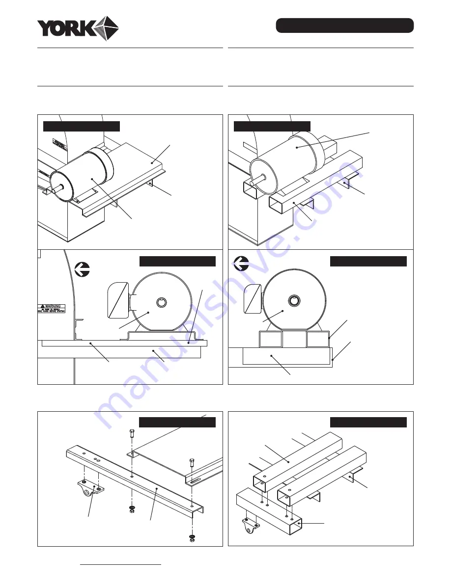
Assembly
M48-100 Drive Assembly
NOTE:
This elevator model will have either a motor
mount or motor mount tubing. Follow the instructions at
right that correspond with your installation.
NOTE:
The location where the torque arm foot attaches
to the torque arm bracket or torque arm tubing may vary
depending on the reducer size.
a2) Install Motor to Tubing
MOTOR
ELEVATOR
BEARING
ANGLE
MOTOR MOUNT
TUBING
Right Hand Drive
MOTOR MOUNT
TUBING
ELEVATOR
BEARING
ANGLE
TORQUE ARM TUBING
Toward Head
Right Hand Drive
MOTOR
a1) Install Motor to Motor Mount
MOTOR MOUNT
MOTOR
ELEVATOR
BEARING
ANGLE
Right Hand Drive
Toward Head
Right Hand Drive
TORQUE ARM
BRACKET
ELEVATOR BEARING
ANGLE
MOTOR
MOTOR
MOUNT
b1) Install the Torque Arm Bracket
TORQUE ARM
FOOT MOUNT
TORQUE ARM
BRACKET
MOTOR
MOUNT
Right Hand Drive
b2) Install the Torque Arm Tubing
MOTOR
MOUNT
TUBING
TORQUE ARM
TUBING
ELEVATOR
BEARING
ANGLE
Right Hand Drive