System Overview ProSafe-COM 3.00
37 of 49
5.4 ProSafe-PLC forcing statuses
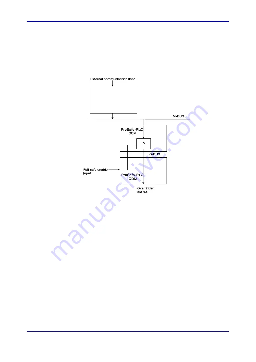
ProSafe-PLC has software facilities to enable forcing statuses.
The Fail-safe enable is typically connected to an input channel of a CDM. This input will typically be linked
to logic in the CCM (basically a logical AND gate) to which also the override output from the ProSafe-COM
is connected (originating from external communication lines)
The CCM is connected to the M-BUS and receives write commands from the ProSafe-COM. The following
picture gives an impression:
ProSafe-COM
Figure 26: Override facility in ProSafe-PLC
5.5 Status acquisition on Y-net
In a Y-net configuration the status of the ProSafe-SLS can be scanned at regular time intervals.
Five different kinds of status data can be collected:
•
Digital input data
The digital input module (MC-573) performs Digital data acquisition.
•
Digital output data
The digital output module (MC-576) executes write commands.
•
Analogue input data
The analogue input module (MC-562) will perform the Analogue status acquisition.
•
Matrix panel input
The matrix panel input controller (MI-983) reads operator’s input.
•
Matrix panel output
The matrix panel output controller (MO-986) sets lamp outputs.
This paragraph describes some more details of this mechanism for the ProSafe-SLS safety system.
Each Y-net can support maximally 120 ProSafe-SLS or matrix panel control modules. ProSafe-COM
scans all Y-net modules through the Y-net.
All Rights Reserved.
©
Copyright Yokogawa Europe Solutions B.V.
TI48J01A00-00E Oct 2010


