


ii
IM MV100-17E
How to Use this Manual
Structure of the Manual
The structure of this User’s Manual is as follows.
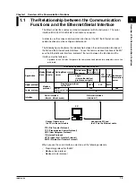
Chapter 1
Overview of the Communication Functions
Describes the relationship between the communication functions and the interface and
provides an outline of the communication functions.
Chapter 2
Using the Ethernet Interface
Describes the specifications and setup procedures of the Ethernet interface. Describes the
FTP client function, Web server function, and e-mail transmission function. Also describes
how to display the log screen.
Chapter 3
Using the Serial Interface (Option)
Describes the functions, specifications, and setup procedures of the serial interface (option).
Two types of serial interfaces, RS-232 and RS-422A/485 are available.
Chapter 4
Using the Modbus Protocol
Describes the specifications and setup procedures of the Modbus protocol and the status
indication screen of the Modbus master.
Chapter 5
Commands
Describes each command that can be used.
Chapter 6
Response
Describes the data format of the panel setup information and measured/computed data that
are output from this instrument.
Chapter 7
Status Report
Describes the status information.
Appendix
Provides an ASCII character code table, the flow of operation when outputting data from MV, a
list of error messages, and the login process.
Index
Provides an index.
Conventions Used in this Manual
Unit
•
k Denotes 1000. Example: 5 kg, 100 kHz
•
K Denotes 1024. Example: 720 KB (Storage capacity of floppy disks)
Symbols
The following symbols are used in this manual.
Affixed to the instrument. Indicates danger to personnel or
instrument and the operator must refer to the User’s Manual.
The symbol is used in the User’s Manual to indicate the
reference.
WARNING
Describes precautions that should be observed to prevent injury
or death to the user.
CAUTION
Describes precautions that should be observed to prevent minor
or moderate injury, or damage to the instrument.
Note
Provides important information for the proper operation of the
instrument.


