
2-5
IM 2558A-01EN
Features
3
2
1
4
5
6
7
8
9
10
11
12
13
14
15
16
App
Index
2.4 Deviation and Presets
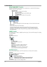
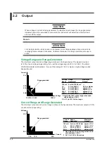
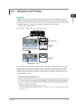
Deviation
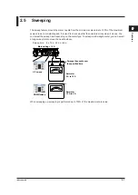
This feature is used to check the relative error (deviation) of the meter scale calibration. If the meter
needle is not pointing accurately to the appropriate scale mark, you can turn a deviation dial on the
front panel to finely adjust the voltage or current output level or the frequency so that the needle points
accurately to the mark. The amount of fine adjustment is displayed as the deviation.
Deviation setting range: ±20.00%
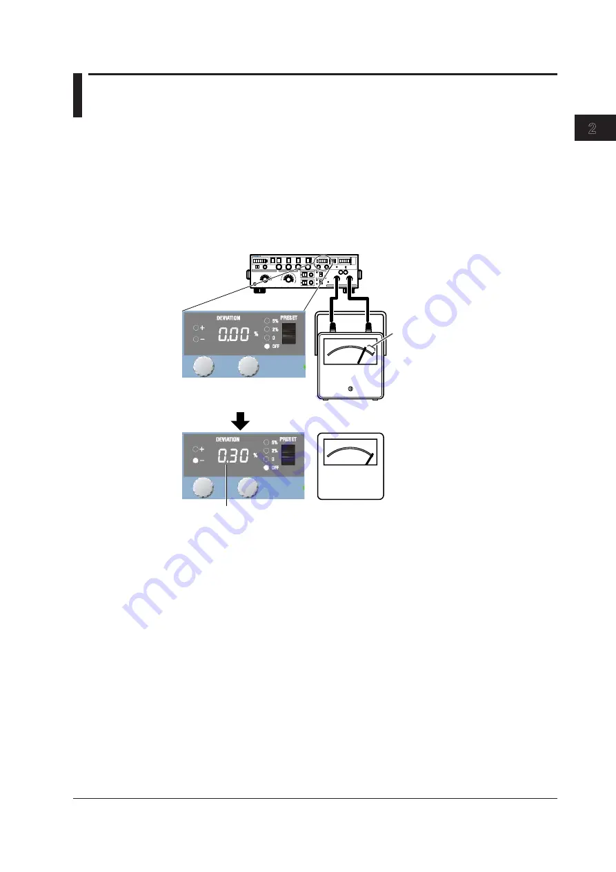
Setup example: Main setting = 10 A, divider value n/m = 1
Ammeter
9.97 A
Main setting = 10 A
Ammeter
10 A
Error (deviation)
Use the deviation dial to align
the meter needle to the accurate
scale position.
The deviation is –0.30%.
In the example above, before fine adjustment, the meter needle is pointing to 9.97 A, which is 0.30%
smaller than the 10 A current output from the 2558A. The deviation polarity (the sign) of the 2558A
indicates whether the target device indication is larger or smaller than the accurate position. In this
example, because the meter is pointing to a value that is 0.30% smaller than the 2558A output value,
the 2558A displays –0.30%.
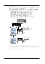
Deviation at Each Calibration Point
When the deviation feature is used in conjunction with the output divider feature explained in section
2.3, you can check at each calibration point the deviation in reference to the maximum scale value.
Note that if the frequency is set to FREQUENCY METER MIN or FREQUENCY METER MAX, the
deviation is in reference to the span.
When the maximum scale value is 10 A, 1% is 0.1 A.
If you are using the output divider feature at n = 2 and m = 10, when 2 A is being output, 1% will
also be 0.1 A.


