Link CX-24 User’s Manual
Version 1.0
Page 34
February 2004
the Link CX-24, it starts transmitting.
36 Connect the power, DS-3 and/or Ethernet cables to the Link CX-24. See Figure 1.3 and Table 1.2 for
the locations and descriptions of the Link CX-24 connectors.
37 Check the LEDs for proper operation. See Figure 1.3 and Table 4.2 for the locations and descriptions
of the Link CX-24 LEDs:
•
When power is properly applied to the Link CX-24, the PWR/LCL ALARM LED will be on.
•
Because the radio link has not yet been established, the RF LINK LED should be off.
•
When the DS-3 equipment is or is not transmitting data to the Link CX-24, the DATA LED should
be on or off, respectively.
•
When the Ethernet equipment is transmitting data to the Link CX-24, the ENET 1 and/or ENET 2
LEDs should be on or flashing. When the Ethernet equipment is not transmitting data to the Link
CX-24, the ENET 1 and/or ENET 2 LEDs should be off or flashing as local data is received.
If any of these conditions is not true, troubleshoot the associated equipment and cables.
2.13.3 Grounding the Link CX-24
The Link CX-24 has a grounding lug. Make sure it is connected to a good earth ground using the
guidelines in Appendix D.
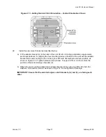
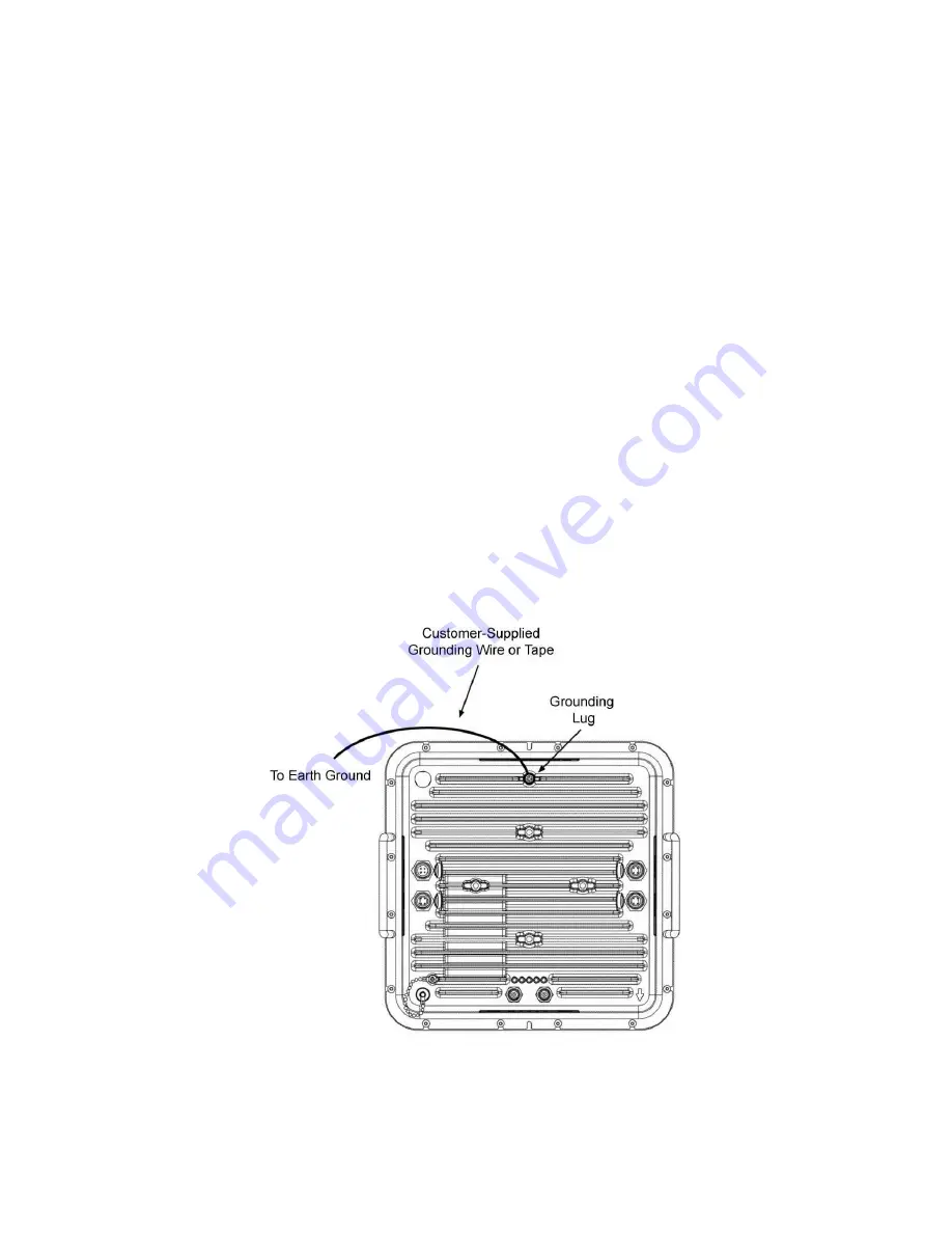
38 Following the guidelines in Appendix D, connect a customer-supplied solid wire or tape (not braided)
grounding wire to the grounding lug on the back of the Link CX-24. See Figure 2.16 for the grounding
lug location. Connect the other end of this cable to a proper grounding point.
Figure 2.16 – Connecting an Earth Ground to the Link CX-24
2.13.4 Sealing the Data and Power Cable Connectors
The cables that are terminated outdoors must be sealed at each exposed end to prevent moisture

