Link CX-24 User’s Manual
Version 1.0
Page 12
February 2004
Safety Warning
This antenna/transmitter device must be fixed-mounted on outdoor
permanent structures with a separation distance of at least 2 meters
(6.56 feet) from all persons. Users and installers must adhere to the
antenna installation instructions and transmitter operating conditions in
order to comply with the FCC’s RF exposure requirements.
Section 2
Installation
2.1 Introduction
The Link CX-24 is intended for professional installation only. However, this manual is also designed for
personnel who plan, operate and administer the Link CX-24 communication system. Please review the
entire manual before powering up or deploying any Link CX-24.
Note:
It is strongly recommended that you configure and test the units prior to deploying them in the
field. Set up a “mini-network” that resembles your actual configuration as close as possible.
By using such a mock-up, troubleshooting potential problems will be much easier than if you
already installed the equipment in the field. Read through this entire Section 2 to understand
how to install the hardware.
2.2
Planning a Link CX-24 Network
As described in Section 1.8, the Link CX-24 can be used to support a number of applications. However,
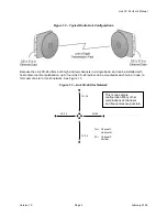
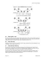
the most common configuration is a point-to-point network. Point-to-point configurations (Figure 1.1) are
easiest to plan and implement, as the radio links merely transmit industry-standard formatted data from
one location to another.
Generally, the common points to consider when planning a Link CX-24 network are:
Line of Sight:
Unlike some frequency bands, the Link CX-24 radios must be within line of sight of each
other. That is, the far-end antenna must be visible from the near-end antenna. If there are trees,
buildings, mountains, or other obstructions between the two antennas, the Link CX-24s on each end of
the radio link will be unable to communicate with each other. Make sure the Link CX-24 radios used in
each radio link are within line of sight of each other. Refer also to the Fresnel Zone Clearance section that
follows.
Fresnel Zone Clearance:
There must be sufficient open space around the direct line of sight to minimize
interference with the radio beam. At a minimum, 60% of the first Fresnel zone of the path should be clear.
Even with clear line-of-sight, objects still may be near enough to the transmission path to cause problems.
Obviously, objects that stand directly in the transmission path obstruct the beam, causing a drop in signal
strength at the receiving end; in addition, objects and reflective surfaces that are in near proximity to the
path can cause signal interference and attenuation of the received signal.
Fresnel zones define the amount of clearance required for obstacles. These zones are series of
concentric ellipsoid surfaces that surround the straight-line path between the two antennas. The first
Fresnel zone is defined as the surface containing every point for which the distance from the transmitter
to any reflection point on the surface and then on to the receiver is one-half wavelength longer than the
CAUTION

