Link CX-24 User’s Manual
Version 1.0
Page 2
February 2004
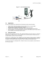
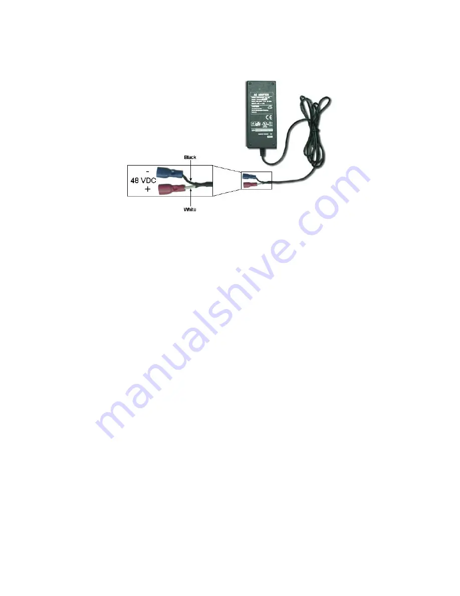
Figure 1.1 – Link CX-24 Power Supply
1.4 Applications
The Link CX-24 product line is designed to serve the following communications markets:
•
Internet Access and Backhaul Systems: Used by Internet Service Providers (ISPs).
•
Private Networks: Wireless Bridged LANs and WANs.
•
PCS/PCN and Cellular Networks: High-speed links between base stations.
•
Wireless Local Loop Networks: Fixed wireless, used by Local Exchange Carriers (LECs).
•
Business Bypass or Local Exchange Bypass: Provided by Competitive Access Providers (CAPs)
and Competitive Local Exchange Carriers (CLECs).
1.5 System
Overview
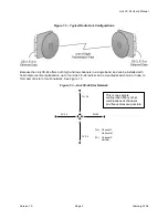
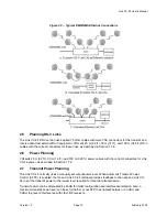
Each Link CX-24 consists of a Link CX-24 radio, with integral antenna as shown in Figure 1.2, along with
external power and data cabling. In a typical installation, the Link CX-24 radio with integral antenna is
mounted outdoors, usually on a tower or building.
See Figure 1.2. A radio system, or link, contains two Link CX-24 radios with integral antenna, installed at
each end of the link, separated by a line of sight transmission path. Frequency band, terrain, actual line-
of-sight and environmental conditions influence the range of operation and path performance.
The Link CX-24 carries one full-duplex DS-3, or Ethernet channel, and is powered by a 48-watt external
48 VDC power supply.


