Link CX-24 User’s Manual
Version 1.0
Page 16
February 2004
2.7.1 Maximum Link CX-24 Power Output
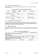
The Link CX-24 can be ordered in two different configurations. Table 2.1 shows the maximum power
output for each case.
Table 2.1 – Maximum Power Output by Model Configuration
Model
Frequency
Band
Link
Carries
Antenna Max
Tx
Power
CX-DS3-24-HI
CX-DS3-24-LO
24.05-24.250GHz
--
Per FCC
Regulations
DS-3
(45 Mbps)
Integral
0 dBm +34.5 dBi =
+34.5 dBm Average EIRP
CX-ETH-24-HI
CX-ETH-24-LO
24.05-24.250GHz
--
Per FCC
Regulations
Ethernet
(45 Mbps)
Integral
0 dBm +34.5 dBi =
+34.5 dBm Average EIRP
2.7.2 Calculating the Required Transmit Power
The Link CX-24 will normally use the maximum transmit power listed in Table 2.1, but may need to be
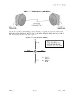
attenuated when there are other receivers beyond the remote Link CX-24 terminal (for instance, in a
mesh network). In this case, the professional installer must use the free-space calculation to determine
the actual Maximum Transmit Power to prevent interference.
2.8
Radio Link Planning
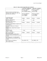
As described in Section 1.7, each radio link requires a Link CX-24 at each end of the link. Before you start
installing the Link CX-24s, make a copy of Table 2.2 and fill in the information for both ends of the radio
link:
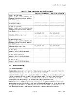
Table 2.2 – Radio Link Planning Worksheet
Link CX-24 1 - High
Link CX-24 2 - Low
Information Common to Both Link CX-24 Radios
Radio Link Name:
Radio Link Information:
Radio Link Polarization (pick one, must be the same for both):
HORIZONTAL
VERTICAL
Radio Link Payload (as ordered, must be the same for both):
DS-3
Ethernet
Information Unique to Each Link CX-24 Radio
Model Number
(see Link CX-24 Label & Table 1.1)
CX- _ _ _ -24- _ _
(high band)
CX- _ _ _ -24- _ _
(low band)

