4.1 Outline
4-2
4.1
Outline
You can set the range of the rotational coordinate system for position data (command position
(CPOS) and feedback position (APOS)) from the host controller in SERVOPACK parameters.
The coordinates will be in the range that is set with Pn87C (First Rotational Coordinate) and
Pn87A (Last Rotational Coordinate).
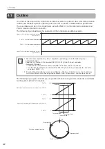
The following figure illustrates the operation of the rotational coordinate system.
The following figure gives an example of operation when the range of the rotational coordinates
for the system is 360
°
(1 rotation).
1. The rotational coordinate system is enabled by performing one of the following steps.
Absolute Encoder
Send the Turn Sensor ON command (SENS_ON: 23h) from the host controller.
Incremental Encoder
•
Send the Zero Point Return command (ZRET: 3Ah) from the host controller.
•
Use the Set Coordinates command (POS_SET: 20h) from the host controller to set a refer-
ence point (REFE = 1).
2. If the rotational coordinate system is enabled (i.e., Pn87A or Pn87C is not set to 0), software
limits and software limit checking are disabled in Pn801 (Application Function Selections 6).
Lower limit of rotational coordinate
s
y
s
tem
(-5
3
6,870,912)
Upper limit of rotational coordinate
s
y
s
tem
(+5
3
6,870,911)
Pn87C: Fir
s
t Rotational Coordinate
Pn87A: La
s
t Rotational Coordinate
Important
Target po
s
ition 2
Target po
s
ition 2
Target po
s
ition 2
3
59°
Pn87A
Pn87C
Pn87A
Pn87C
0°
3
59°
3
59°
0°
0°
Machine rotational po
s
ition
Current po
s
ition
Current po
s
ition
Current po
s
ition
Target po
s
ition 1
Target po
s
ition 1
Rotational coordinate of feedback po
s
ition (APO
S
)
Rotational coordinate of command po
s
ition (CPO
S
)
Target po
s
ition 1


