


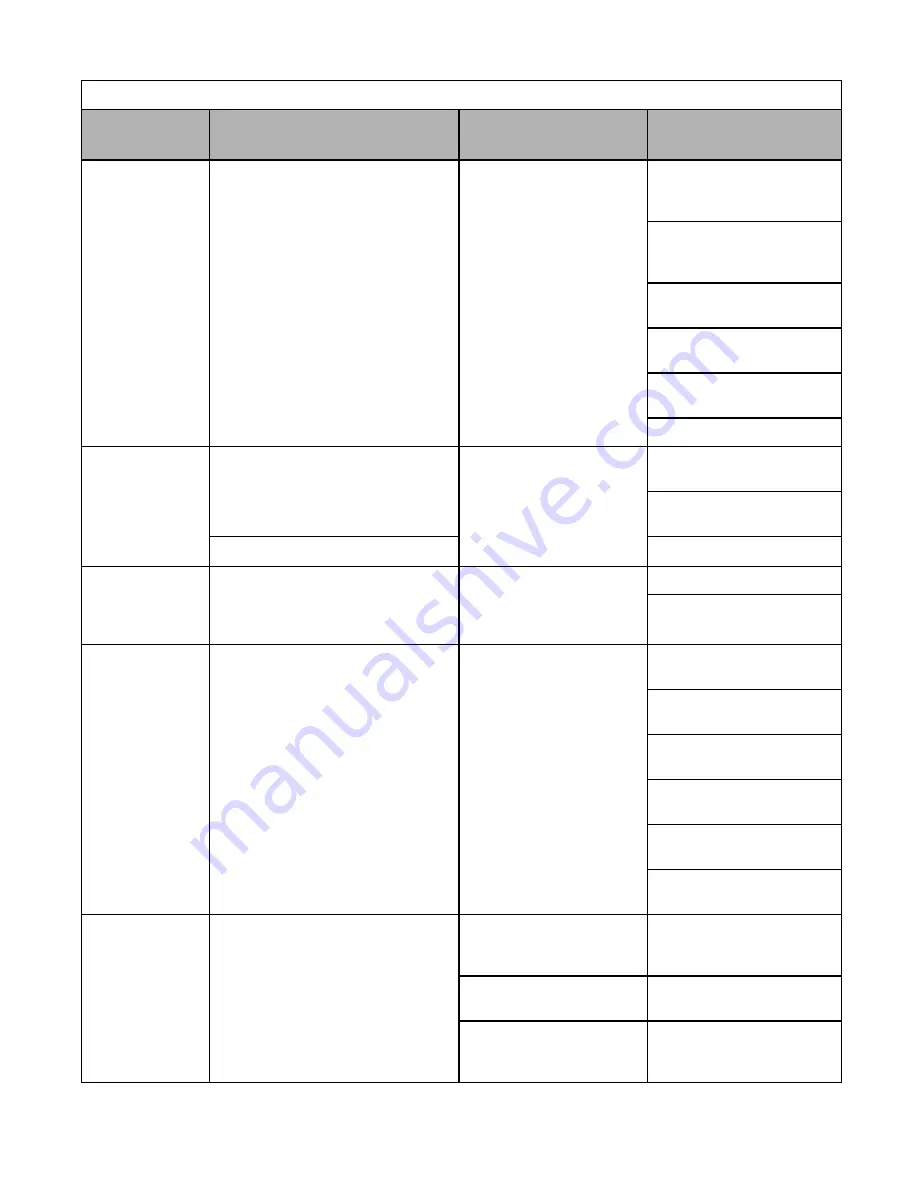
Diagnostic & Troubleshooting 6 - 9
FBL
Feedback Loss
PI Feedback Loss
This fault occurs when PI Feedback Loss
Detection is programmed to fault
(b5-12 = 2) and the
PI Feedback < PI Feedback Loss Detection
Level (b5-13) for the PI Feedback Loss
Detection Time (b5-14)
PI Feedback source
(e.g. transducer, sensor, build-
ing automation signal) is not
installed correctly or is not
working
Verify Drive is programmed to
receive the PI Feedback source
signal
Check to ensure the PI Feedback
source is installed and working
properly
Check the motor for a phase-to-
phase short
Check the Drive for a phase-to-
phase short at the output
Verify C1-01 and C1-02 are set
correctly
Check load conditions
OH
Heatsnk Overtemp
(Flashing)
Cooling Fin/Cooling Fin Fan Overheat
The temperature of the Drive cooling fin
exceeded the temperature programmed in
parameter L8-02
Cooling fan(s) are not working,
high ambient temperature, a
heating unit in close proximity
to Drive is present
Check for dirt build-up on the
fans and cooling fins
Reduce the ambient temperature
around the Drive
Drive Internal Cooling Fan
Remove the heating unit
OH2
Over Heat 2
(Flashing)
Drive overheat pre-alarm signal is input
from a multi-function digital input terminal
An external overheat condition
exists connected to one of the
multi-function input terminals
S3, S4, S5, S6 or S7
Check for an external condition
Verify the program parameters
H1-01 thru H1-05
OH3
Motor Overheat 1
(Flashing)
Motor Overheating Alarm
The Drive stops or continues operation
according to the setting of L1-03.
Overheating of motor
Recheck the cycle time and the
size of the load
Recheck the accel/decel time
(C1-01 and C1-02)
Recheck the V/F pattern (E1-01
thru E1-13)
Recheck the motor rated current
value (E2-01)
Check the digital operator
connector
Verify the setting of
o2-06
OV
DC Bus Overvolt
(Flashing)
DC Bus Overvoltage
208-240Vac: Trip point is
≥
400Vdc
480Vac: Trip point is
≥
800Vdc
High input voltage at R/L1,
S/L2 and T/L3
Check the input circuit and
reduce the input power to within
specifications
Extend the time in C1-02
The deceleration time is set too
short
Power factor correction
capacitors are being used on the
input to the Drive
Remove the power factor correc-
tion capacitors
Table 6.2 Alarm Displays and Processing
Digital
Operator Display
Description
Cause
Corrective Action
Summary of Contents for P7
Page 1: ...P7 Drive User Manual Model P7U Document Number TM P7 01...
Page 58: ...Electrical Installation 2 30...
Page 74: ...Digital Operator 3 16...
Page 84: ...Start Up 4 10 Notes...
Page 144: ...Programming 5 60 Notes...
Page 210: ...Capacity Related Parameters B 6 Notes...
Page 238: ...Spare Parts F 4 Notes...
Page 244: ...EMC Compatibility G 6 Notes...