


Diagnostic & Troubleshooting 6 - 6
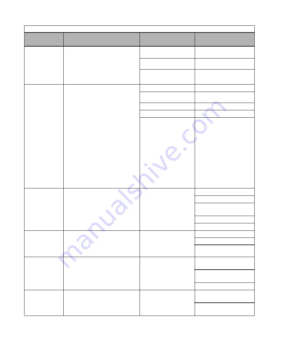
OV
DC Bus Overvolt
DC Bus Overvoltage
208-240Vac: Trip point is
≥
400Vdc
480Vac: Trip point is
≥
800Vdc
High input voltage at R/L1,
S/L2 and T/L3
Check the input circuit and reduce the
input power to within specifications
The deceleration time is set
too short
Extend the time in C1-02
Power factor correction
capacitors are being used on
the input to the Drive
Remove the power factor
correction capacitors
PF
Input Pha Loss
Input Phase Loss
Drive input power supply has an open phase
or has a large imbalance of input voltage
Open phase on input of the Drive Check the input voltage
Loose terminal screws at
R/L1, S/L2 or T/L3.
Tighten the terminal screws
Momentary power loss occurred
Check the input voltage
Input voltage fluctuation too large
Check the input voltage
Parameter L8-06 value is set
incorrectly
Verify parameter L8-06 is set
correctly per the kVA tables on
pages C-2 and C-3. Adjust L8-06
according to your application.
The higher the value the less
sensitive it becomes.
CAUTION: Changing this
parameter from the factory
default setting may cause
Drive failure and void the
product warranty. (Consult
the factory for application
assistance).
PUF
DC Bus Fuse Open
DC Bus Fuse
Detects if the DC bus fuse has opened
Shorted output transistor(s) or
terminals
Remove power from the Drive
Disconnect the motor
Perform the checks without
power in Table 6.6
Replace the shorted component(s)
Replace the defective fuse
RH
DynBrk Resistor
Dynamic Braking Resistor
The protection of the dynamic braking
resistor based on setting of L8-01
Overhauling load, extended
dynamic braking duty cycle,
defective dynamic braking
resistor
Verify dynamic braking duty cycle
Monitor DC bus voltage
Replace dynamic braking
resistor
RR
DynBrk Transistr
Dynamic Braking Transistor
The dynamic braking transistor failed
Shorted dynamic braking
transistor, high DC bus
voltage, defective dynamic
braking resistor
Cycle power off and on to the
Drive
Replace defective dynamic
braking transistor or resistor
Monitor DC bus voltage
UL3
Undertorq Det 1
Undertorque Detection 1
Drive output current < L6-02 for more than
the time set in L6-03
Motor is underloaded
Ensure the values in L6-02 and
L6-03 are appropriate
Check application/machine
status to eliminate fault
Table 6.1 Fault Displays and Processing
Digital
Operator Display
Description
Cause
Corrective Action
Summary of Contents for P7
Page 1: ...P7 Drive User Manual Model P7U Document Number TM P7 01...
Page 58: ...Electrical Installation 2 30...
Page 74: ...Digital Operator 3 16...
Page 84: ...Start Up 4 10 Notes...
Page 144: ...Programming 5 60 Notes...
Page 210: ...Capacity Related Parameters B 6 Notes...
Page 238: ...Spare Parts F 4 Notes...
Page 244: ...EMC Compatibility G 6 Notes...