


60
HB700 | CPU | PMC921xEx | en | 24-04
Hardware description
iC9200 Series
Structure > Interfaces
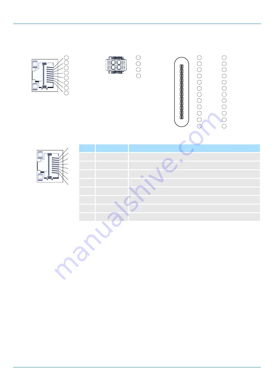
X1: EtherCAT port
1
2
3
4
5
6
7
8
3.2.2
Interfaces
X1/X2 X3/X4
TD+
TD-
RD+
n.c.
n.c.
RD-
n.c.
n.c.
DA+
DA-
DB+
DC+
DC-
DB-
DD+
DD-
X6
+ DC 24V
+ DC24V
0V
0V
1
2
3
4
1
2
3
4
GND
A
TX1+
TX1-
VBUS
CC1
D+
D-
n.c.
VBUS
RX2-
RX2+
GND
1
2
3
4
5
6
7
8
9
11
12
10
GND
B
TX2+
TX2-
VBUS
CC2
D+
D-
n.c.
VBUS
RX1-
RX1+
GND
1
2
3
4
5
6
7
8
9
11
12
10
1
A
12
B
2
11
3
10
4
9
5
8
6
7
7
6
8
5
9
4
10
3
11
2
12
1
X7
1
2
3
4
5
6
7
8
8pin RJ45 jack:
Pin
Signal
Description
1
TD+
Send data +
2
TD-
Send data -
3
RD+
Receive data +
4
n.c.
reserved
5
n.c.
reserved
6
RD-
Receive data -
7
n.c.
reserved
8
n.c.
reserved
■
The CPU has an integrated Ethernet communication processors with EtherCAT con-
troller.
■
You can use the EtherCAT controller in an EtherCAT system as:
–
EtherCAT master (only PMC921xE0)
–
EtherCAT FSoE master (only PMC921xES)
■
It is connected via the integrated EtherCAT port X1.
■
Connect this interface with the RJ45 jack "IN" of your EtherCAT slave station.
■
EtherCAT uses Ethernet as transfer medium. Standard CAT5 cables are used. Here
distances of about 100m between two stations are possible.
■
An EtherCAT network always consists of an EtherCAT master and an various number
of EtherCAT slaves (coupler).
■
Each EtherCAT slave has an "IN" and "OUT" RJ45 jack. The arriving EtherCAT cable
from the direction of the master is to be connected to the "IN" jack. The "OUT" jack
is to be connected to the next station. With the respective last station the "OUT" jack
remains free.
Summary of Contents for iC9200 Series
Page 211: ...7 Appendix...
Page 212: ......
Page 214: ...214 HB700 CPU PMC921xEx en 24 04 Checklists Deployment CPU iC921xM FSoE iC9200 Series...