background image

A5-3

H1

H

4-d

0.06
(1.5)

H2

W1

W

W2

0.09
(2.20)

D

0.33
(8.5)

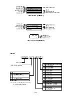
Model

Size

Dimensions in inches (mm)

Weight

Heat Loss (W)

Voltage

CIMR-

Lbs.

Heat-

Class

V7*U

MV

HP

W

H

D

W1

H1

H2

W2

H3

H4

d

(kg)

sink

Unit Total

Fig.

25P5

A025

7.5

7.09

10.24

6.70

6.46

9.61

0.31

0.31

M5

11.45

170.4

79.4 249.8

3

230V

(180)

(260)

(170) (164) (244)

(8)

(8)

(5.2)

3-phase

27P5

A033

10

7.09

10.24

6.70

6.46

9.61

0.31

0.31

M5

11.89

219.2

98.9 318.1

3

(180)

(260)

(170) (164) (244)

(8)

(8)

(5.4)

45P5

B015

7.5

7.09

10.24

6.70

6.46

9.61

0.31

0.31

M5

10.14

168.8

87.7 256.5

3

460V

(180)

(260)

(170) (164) (244)

(8)

(8)

(4.6)

3-phase

47P5

B018

10

7.09

10.24

6.70

6.46

9.61

0.31

0.31

M5

10.58

209.6

99.3 308.9

3

(180)

(260)

(170) (164) (244)

(8)

(8)

(4.8)

* 230/460V class 7.5/10 HP drives can be used as “IP00” if the top and bottom covers are removed.

GPD 315/V7 Enclosed wall mounted type (NEMA 1)

Fig. 3

When drives include network communications option board, add 1.5" to drive depth.

Summary of Contents for GPD315/V7-4X

Page 1: ...GPD 315 V7 and V7 4X Technical Manual...

Page 2: ...01 1 n002 0 n003 1 n004 2 n005 0 n006 0 n007 0 n008 0 n009 0 n010 0 n011 60 n012 230 460 n013 60 n014 Note 2 n015 Note 2 n016 Note 2 n017 Note 2 n018 0 n019 n020 10 0 n021 n022 n023 0 n024 6 00 n025 0...

Page 3: ...ng to standards and specifications published in YASKAWA s manual NO OTHER WARRANTY EXPRESS OR IMPLIED IS OFFERED YASKAWA assumes no liability for any personal injury property damage losses or claims a...

Page 4: ......

Page 5: ...Accel Decel Time 5 2 5 3 Accel Decel S Curve Characteristics 5 3 5 4 Auto Restart 5 4 5 5 Carrier Frequency 5 5 5 6 Critical Frequency Rejection 5 6 5 7 DC Injection Braking 5 7 5 8 Frequency Referen...

Page 6: ...quency Reference Loss Detection 5 57 5 34 Undertorque Detection 5 58 6 FAULT DIAGNOSIS AND CORRECTIVE ACTIONS 6 1 6 1 General 6 1 6 2 Displaying Fault Sequence 6 8 Appendix 1 LISTING OF PARAMETERS A1...

Page 7: ...ous situation which if not avoided could result in death or serious injury to personnel WARNING Indicates a potentially hazardous situation which if not avoided may result in minor or moderate injury...

Page 8: ...ducts in conforming to standards and specifications published in YASKAWA s manual NO OTHER WARRANTY EXPRESS OR IMPLIED IS OFFERED YASKAWA assumes no liability for any personal injury property damage l...

Page 9: ...rnal Run Stop signals Before using the initialization function of constant n001 know your control wiring configuration 10 Factory 2 Wire Control Initialization Maintained RUN Contact 11 Factory 3 Wire...

Page 10: ...wer Never connect main circuit output terminals T1 T2 and T3 to AC main circuit power supply All parameters have been factory set Do not change their settings unnecessarily Do not perform a HIPOT or w...

Page 11: ...ide to installing programming and using the Yaskawa GPD315 V7 V7 4x 12 hereafter referred to as the Drive It highlights several common installation configurations Detailed information on all drive fea...

Page 12: ...his method the drive can be started and stopped using an external remote signal Example 2 Page 4 3 wire Digital Operator This method is the same as Example 2 above but uses pushbuttons instead Example...

Page 13: ...omes from the digital operator pot The drive can be started by pressing the RUN key on the digital operator The drive can be stopped by pressing the STOP key on the digital operator The direction of t...

Page 14: ...ays the error message EF If the drive is put in the Local mode using the LO RE quick start LED the drive will behave the same as illustrated in Example 1 Table 3 Programming Required For Remote 2 wire...

Page 15: ...the drive running at any speed If the drive is put in the Local mode using the LO RE quick start LED the drive will behave the same as illustrated in Example 1 Table 4 Programming Required For Remote...

Page 16: ...the drive is put in the Local mode using the LO RE quick start LED the drive will behave the same as illustrated in Example 1 Table 5 Programming Required For Remote 2 wire Sequence Remote 4 20 mA Ref...

Page 17: ...Terminal FV 0V 0 Hz 5V 30 Hz 10V 60 Hz If the drive is put in the Local mode using the LO RE quick start LED the drive will behave the same as illustrated in Example 1 Table 6 Programming Required For...

Page 18: ...parameter n027 Table 7 Programming Required For Remote 2 wire Sequence Multiple References Parameter Display Description n001 10 The drive will perform a 2 wire reset CAUTION Setting this value will r...

Page 19: ...e motor starter control A momentary closure of a normally open run switch latches the drive in the RUN mode STOP switch must be closed or the drive will not accept the momentary RUN command A momentar...

Page 20: ...xvi...

Page 21: ...itialization Momentary START STOP Contact Entering either Initialization code resets all parameters to factory settings and automatically returns parameter n001 setting to 1 If the Drive is connected...

Page 22: ......

Page 23: ...is received must be reported immediately to the commercial carrier who transported the equipment Assistance if required is available from your sales representative Do not install a drive that is damag...

Page 24: ...mensions and mounting dimensions refer to the DIMENSIONS section of Appendix 5 4 Allowable intake air temperature to the Drive Open chassis type 10 C to 50 C Enclosed wall mounted type 10 C to 40 C 5...

Page 25: ...lock Control Circuit Block SW2 2 Analog Input Current Voltage Selector SW2 1 Terminating Resistor for Serial Communication Status Indicator LEDs Digital Operator Speed Pot SW1 Digital Input Type Short...

Page 26: ...2 of 3 Ground Terminal Main Circuit Block Control Circuit Block SW2 2 Analog Input Current Voltage Selector SW2 1 Terminating Resistor for Serial Communication Status Indicator LEDs Digital Operator...

Page 27: ...ontinued 1 4 PHYSICAL INSTALLATION Figure 1 1 Main Circuit Terminals Sheet 3 of 3 Model CIMR V7IU 20P1 20P2 20P4 20P7 MV A001 A002 A003 A005 Model CIMR V7IU 21P5 22P2 40P2 40P4 40P7 41P5 42P2 MV A008...

Page 28: ...NEVER allow wire leads to contact metal surfaces Short circuit may result NEVER connect power factor correction capacitors to the drive output Consult Yaskawa when connecting noise filters to the dri...

Page 29: ...e lb in N m size mm2 AWG mm2 AWG MA MB MC M3 4 44 to 5 33 twisted wire 0 5 to 1 25 20 to 16 0 75 18 Common 0 5 to 0 6 single 0 5 to 1 25 20 to 16 Shielded to S1 to S7 P1 P2 SC 1 94 to 2 21 twisted wir...

Page 30: ...440 460 480V L3 T at 50 60 Hz T1 U T2 V Main circuit output 230V Drive 0 200 208 220 230V T3 W 460V Drive 0 400 440 460 480V B1 For connection of braking resistor option B2 1 DC Reactor terminals 2 D...

Page 31: ...oss their coils All DC relays contactors and solenoids should have diodes installed across their coils Continued 1 4 ELECTRICAL INSTALLATION CORRECT CORRECT NOT ACCEPTABLE C Grounding The drive must b...

Page 32: ...30 KHz maximum pulse input FC Frequency reference input common 0 V MA Multi function contact output NO contact Factory Contact capacity MB Multi function contact output NC contact Setting 250 Vac at 1...

Page 33: ...TO CASE EARTH GROUND SEE NOTE 2 SEE NOTES 3 4 SEE NOTES 3 4 A C MOTOR 1 2 3 4 5 6 IN OUT T3 T2 T1 C1 B1 A1 C2 B2 A2 EARTH GROUND SEE NOTE 2 SEE NOTE 6 DC REACTOR 1 2 L31 L21 L11 Figure 1 3 Customer C...

Page 34: ...or EMC Directive using AC Drive Products Table 1 4 and Figure 1 4 show the line filter list for EMC standards and the installation wiring of the Drive and line filter Table 1 4 Line Filters for EMC St...

Page 35: ...1 13 Continued 1 4 ELECTRICAL INSTALLATION U V W Figure 1 4 Installation of Line Filter and Drive...

Page 36: ...nction n036 n037 meets standards set by UL and CUL for motor thermal overload protection If local code requires a separate mechanical overload protection an overload relay should be installed interloc...

Page 37: ...CY MULTI FUNCTION CONTACT INPUT MA MB MC RUNNING FAULT FOR DYNAMIC BRAKING See Note 6 FOR DC REACTOR See Note 7 See Note 5 P2 SPEED COINCIDENCE See Note 8 See Note 5 MODBUS COMMUNICATIONS RS485 422 19...

Page 38: ...parate mechanical overload protection an overload relay should be installed interlocked with the Drive as shown It should be the manual reset type to prevent automatic restart following a motor fault...

Page 39: ...Note 6 FOR DC REACTOR See Note 7 See Note 5 P2 SPEED COINCIDENCE See Note 8 See Note 5 MODBUS COMMUNICATIONS RS485 422 19 2 KBPS MAX See Note 4 See Note 1 1RH MANUAL SPEED 2K 0 10VDC or 4 20mA 1OL Se...

Page 40: ...1 18...

Page 41: ...1 Open Loop Vector Control method should be used for most constant torque applications of the Drive With this control method there is excellent starting torque and excellent speed regulation The start...

Page 42: ...s lit on the digital operator DSPL Set drive for Open Loop Vector control This is accomplished by setting n002 1 Press then DATA ENTER V Set motor rated voltage This can be obtained from the nameplate...

Page 43: ...eed P Number of motor poles Example Slip 1800 1725 4 120 Slip 2 5 Press and hold until n106 is displayed on the digital operator Then press Use the keys until the number in the display matches the cal...

Page 44: ...smoothly Motor rotates in correct direction If motor does not rotate in the proper direction stop the motor and remove power from the Drive Switch motor connections T1 U and T2 V at the Drive Motor h...

Page 45: ...the key four times DSPL This completes the startup Make further programming changes as required Press the key to get out of the programming mode DSPL 1 The number in the display may be different than...

Page 46: ...rocedure Set the highest parameter access level This will allow all parameters to be viewed and set Press key until the LED is lit on the digital operator PRGM DSPL Set drive for V f control This is a...

Page 47: ...press DATA ENTER V V DATA ENTER V Set the V f pattern Parameters n011 through n017 set the V f pattern Table 5 4 in section 5 27 lists recommended V f patterns The numbers in parentheses shown in the...

Page 48: ...TA ENTER V Set Parameter n013 Frequency at max voltage point motor rated frequency 60 0 Hz Press then DATA ENTER V PRGM PRGM PRGM PRGM PRGM PRGM PRGM PRGM PRGM 1 Then press DATA ENTER Use the keys unt...

Page 49: ...4 V Press then DATA ENTER V Set Parameter n016 Frequency Minimum 1 5 Hz Press then DATA ENTER V PRGM PRGM PRGM PRGM PRGM PRGM PRGM PRGM PRGM 1 1 1 1 1 1 Then press DATA ENTER Use the keys until the d...

Page 50: ...s T1 U and T2 V at the Drive to change direction Motor has no abnormal vibration or noise Acceleration and deceleration are smooth Unit is not overloaded Displayed current does not exceed drive rated...

Page 51: ...m Before applying a RUN command to the Drive verify that the motor is stopped NEVER use a motor whose full load amps exceeds the Drive rating When starting and stopping the motor use the operation sig...

Page 52: ...3 2...

Page 53: ...FOUT IOUT MNTR F R LO RE PRGM DSPL Digital Operator Potentiometer Pot Display section Data display section Function LED s Press to switch between function LED s RUN DIGITAL OPERATOR JVOP 140 Press to...

Page 54: ...ible during run command See section 4 4 for complete listing of all monitor parameters FWD REV Run Selection Sets the rotation direction of the motor when a Run command is given by the Digital Operato...

Page 55: ...4 MONITOR DISPLAYS 1 Actual display appearance 2 Actual display appearance 3 See section 6 for viewing of fault log contents Term S5 input OPEN Term S6 input CLOSED Term S7 input OPEN Not used Term S...

Page 56: ...4 4...

Page 57: ...9 n033 n034 Jog Reference 5 12 n032 n050 n056 Frequency Reference Selection 5 11 n004 n008 n009 Multi step Speed Setting 5 11 n004 n024 n031 n050 n056 n120 n127 Up Down Frequency Setting 5 10 5 18E n0...

Page 58: ...Term S1 thru S7 Data 27 Accel Decel Time Selection 2 The following table shows which acceleration and deceleration times are selected by each combination of accel decel time select 1 n050 thru n056 1...

Page 59: ...on Actual decel time Set decel time 2 S curve selection The following figure shows FWD REV switching and acceleration deceleration to a stop with S curve active RUN FREQ COMMAND 0 TIME S Curve Charact...

Page 60: ...meter up to the maximum of 10 When set to 0 no auto restarts will be attempted Fault contact will not actuate change state during auto restart attempts The following faults can be automatically reset...

Page 61: ...s establish carrier frequencies of 12f 24f or 36f respectively FcMAX CARRIER FREQUENCY SLOPE FcMIN 0 F1 F2 OUTPUT FREQUENCY 5 5 CARRIER FREQUENCY n175 Reduce carrier at low speed selection Factory Set...

Page 62: ...around each selected prohibited frequency point EXAMPLE Vibration encountered between 30 00 and 36 00 Hz SOLUTION Set n083 to 33 00 This is the center of the problem frequency band Set n086 to 3 00 T...

Page 63: ...and is received the Drive controls motor deceleration according to the Decel Time setting until output frequency reaches the DC injection braking start frequency or Minimum Frequency n016 Then the Dri...

Page 64: ...uency Reference Gain Factory setting 100 Range 0 to 255 Sets the auto speed frequency command gain in increments of 1 n061 Analog Frequency Reference Bias Factory setting 0 Range 100 to 100 10V FREQ R...

Page 65: ...upper and lower limit points EXAMPLE n011 60 Hz 100 n033 80 48Hz Max speed n034 10 6Hz Min speed NOTE n033 must be set to a higher value than n034 100 n033 80 OUTPUT FREQ n034 10 2 5 t 5 9 FREQUENCY R...

Page 66: ...wer must be removed from the Drive before SW2 can be set B Frequency Reference via Digital Presets In order to set the Drive so the frequency reference comes from the digital presets the following par...

Page 67: ...Example 2 Eight preset references Programming n054 6 n055 7 and n056 8 DIGITAL PRESET S7 S6 S5 Selectable Reference 2 Open Open Open n025 Open Open Closed n026 Open Closed Open n027 Open Closed Closed...

Page 68: ...lse Train Input Scaling Factory Setting 2500 Range 100 to 3000 x 10 Hz This parameter scales the incoming frequency on terminal RP by using the following equation Frequency reference Pulse Source Freq...

Page 69: ...l ramp to the output level set by this parameter When an external Jog signal is present it will override the existing operation mode and the Drive will ramp to the level set by this parameter EXAMPLE...

Page 70: ...a data of 1 Run Reverse n051 is set to a data of 2 1 3 Wire control Parameter n052 needs to be set to a data of 0 Run is controlled by a momentary closure on terminal S1 Stop is controlled by a moment...

Page 71: ...e when the frequency reference is controlled by a digital preset n024 SETTING DESCRIPTION 0 key must be pressed in order for the drive to accept the frequency reference 1 key does not have to be press...

Page 72: ...nchronous Transmission parameters Baud rate Selectable from 2400 4800 9600 19 200 BPS n154 Data length Fixed to 8 bits Parity Parity no parity even odd selectable n155 Stop bit Fixed to 1 bit Protocol...

Page 73: ...serial communications link set this to a data of 6 n050 thru n056 Multi function Inputs Data 18 Serial communication Term S2 S6 Digital Operator Selects operation by serial communication or by externa...

Page 74: ...e is also rounded off Setting Frequency Resolution 0 0 1 Hz 1 0 01 Hz 2 30000 100 3 0 1 n153 Modbus Slave Address Factory setting 0 Range 0 to 31 Each slave Drive on the same transmission line must be...

Page 75: ...With power applied to the Drive set parameter n056 35 2 Remove power from the Drive and wait for the charge light to go off 3 Disconnect all wiring terminals R R S S S7 4 Install the following wires...

Page 76: ...SCELLANEOUS PROTECTIVE FUNCTIONS n065 Monitor output Selection Factory Setting 0 Range 0 1 Analog output AM AC can be used as a pulse train output output frequency monitor only n066 Multi function Ana...

Page 77: ...voltage V Load Impedence K ohms 5V 1 5K ohms TO 3 499K ohms 8V 3 5K ohms TO 9 99K ohms 10V 10K ohms or more 5 21 Continued 5 17 MULTI FUNCTION ANALOG MONITOR OUTPUT Term AM AC SETTING DESCRIPTION 0 11...

Page 78: ...r the enter key is pressed A parameter set failure Err will occur if any of the following conditions are detected Two parameters contain the same value n050 thru n056 Both the Accel Decel Hold data 16...

Page 79: ...input 14 Speed Search 1 Closed Speed Search operation from maximum frequency See paragraph 5 18D 15 Speed Search 2 Closed Speed Search operation from set frequency See paragraph 5 18D 16 Accel Decel...

Page 80: ...ote cannot be adjusted from the digital operator B Data 12 External Base Block by N O Contact When either the Forward Run command or Reverse Run command is present and the external Base Block command...

Page 81: ...he speed search begins with the frequency command command that has been set after the search command was received E n101 Speed Search Deceleration Time Factory setting 2 0 Range 0 0 to 10 0 seconds De...

Page 82: ...ax x n033 Freq Ref Upper Limit 100 5 Lower limit speed is from n034 Frequency Reference Lower Limit 6 See section 5 10 for information on the Up Down hold memory EXAMPLE n056 Data 34 Up Down function...

Page 83: ...e multifunction input parameters n050 thru n057 one of the multi function input terminals S1 thru S7 becomes a HOLD command input As long as the HOLD command is present accel and decel are in a prohib...

Page 84: ...IMPORTANT If an open collector output is applied to a DC relay the relay MUST be diode protected as shown in the recommended configuration below 5 19 MULTI FUNCTION OUTPUT TERMINALS Term MA MB MC P1...

Page 85: ...losed Alarm condition is present 11 During coast to stop Closed Drive output base block is active motor is coasting 12 Local Remote Open Frequency and Run Command by ext input Closed Frequency and Run...

Page 86: ...utput contact will close dependent upon the data programmed into n057 n058 or n059 See the appropriate figure below for operation A Speed at Set Frequency B Frequency Detection Low setting n057 n058 o...

Page 87: ...operation after overtorque detection set to 1 or 3 During detection the Digital Operator displays and oL3 alarm blinking To stop the drive at an overtorque detection fault set to 2 or 4 At detection...

Page 88: ...PLE OF OVERTORQUE DETECTION n096 setting 2 Overtorque enabled only at set frequency coast to stop n057 setting 6 Output contact programmed for overtorque detection n096 setting 110 Level at which over...

Page 89: ...2 Wire Control Initialization Maintained RUN Contact 11 Factory 3 Wire Control Initialization Momentary START STOP Contact Entering either Initialization code resets all parameters to factory settings...

Page 90: ...ation Equation 5 22 SLIP COMPENSATION V f 46 35 Hz actual output 1 35 H frequency boost corresponding voltage boost 45 Hz command n110 Motor No Load Current Factory setting See Table A3 1 Range 0 to 9...

Page 91: ...lue set in n093 acceleration resumes In the constant horsepower region actual output frequency max voltage frequency n013 the stall prevention level during acceleration is changed by the following for...

Page 92: ...ed on setting of n094 1 Enabled level at Fmax n011 is n094 x 0 4 E n116 Stall Prevention During Run Accel Decel Time Select Factory setting 0 Range 0 or 1 Setting Function 0 Follows accel decel 1 n019...

Page 93: ...ng is applied immediately before stop If the decel time is too short or the load inertia is too large an overvoltage OV fault may occur on a stop command the decel time must be increased B Data 1 Coas...

Page 94: ...electronic thermal overload function monitors motor temperature based on drive output current and time to protect the motor from overheating When the electronic thermal overload trips an oL1 error oc...

Page 95: ...5 Torque Compensation Iron Loss Factory setting See Table A3 1 Range 0 0 to 6550 W This parameter should be adjusted only when motor capacity and drive capacity are different n109 Torque Compensation...

Page 96: ...Use of motor rated below Drive max output 3 Voltages shown are for 230V motors for other motor voltages multiply all voltage V values by Vmtr 230 i e for a 460V motor multiply by 460 230 2 Max Starti...

Page 97: ...a V f pattern with a straight line from Fmin to FA set FB Fmin The setting of VC is then disregarded and does not affect the V f pattern IMPORTANT The V f parameter settings are checked each time the...

Page 98: ...Range each 0 0 to 400 0 Hz The frequency reference becomes the PID setpoint C Feedback Signal Selection n164 PID Feedback Selection Factory setting 0 Range 0 to 5 Set SW2 2 to I ON SW2 consists of tw...

Page 99: ...to 25 0 This parameter is a multiplier in the output of the PID controller Increasing this parameter will make the PID controller more responsive Be careful not to increase this parameter too much or...

Page 100: ...ponding multi function input terminal S1 thru S6 will disable the PID control At the same time the PID setpoint will become the output frequency and the PID s integrator will reset to zero n050 thru n...

Page 101: ...5 45 PID Block Diagram...

Page 102: ...ded when this parameter is disabled n177 0 preventing the accidental overwriting of parameters stored in the Digital Operator If n177 0 and an upload is attempted n176 rEd or Cpy a PrE error message w...

Page 103: ...s will allow all parameters to be viewed and set Press the key until the LED is lit on the digital operator DSPL Set Parameter Copy Access Selection n177 1 Press and hold until n177 is displayed on th...

Page 104: ...er access level This will allow all parameters to be viewed and set Press the key until the LED is lit on the digital operator DSPL Set Parameter Copy Access Selection n177 1 Press and hold until n177...

Page 105: ...hree times V Press DATA ENTER Press Vfy will blink on the display while verifying DATA ENTER C Verify Function uFy Compares the parameter data stored in the operator with the parameter data in the dri...

Page 106: ...rive capacity in kilowatts This value can be compared to the drive specification number on the drive data nameplate E Software Number Display The software number display allows the user to check the s...

Page 107: ...ameter data in the drive Check to see if the drives are the same type and in the digital operator do not match Ex Copying from a GPD 315 V7 and writing to a GPD 305 J7 ndr Flashing No parameter data i...

Page 108: ...tor synchronous speed P no of motor in increments of 1 RPM poles 3999 max P no of motor poles F Frequency NS motor synchronous speed NOTE If motor synchronous speed exceeds 3999 RPM display holds at 3...

Page 109: ...z n142 Energy Saving Voltage Lower Limit 6 Hz n159 Energy Saving Voltage Upper Limit 60 Hz n160 Energy Saving Voltage Upper Limit 6 Hz These parameters are used to set the output voltage upper and low...

Page 110: ...when n144 is set to 0 n145 Step Voltage of tuning to 100 output voltage n146 Step voltage of tuning to 5 output voltage n143 Time of average KW Parameter n145 n146 sets the voltage fluctuation for on...

Page 111: ...nalog Input is disabled 1 Auxiliary Frequency Reference FREF2 2 Frequency Reference Gain FGAIN 3 Frequency Reference Bias FBIAS 4 Output Voltage Bias VBIAS Factory Setting 0 Range 0 to 4 5 32 Multi Fu...

Page 112: ...aster speed reference input at terminals FR or RP 4 Output Voltage Bias n077 4 VBIAS is added to output voltage after V f pattern is established n078 Multi Function Analog Input Signal Selection n079...

Page 113: ...ction applies to frequency references at terminal FR RP or 2CN Multi Function Analog Input Undertorque detection is used to compare Drive output current torque with the undertorque detection level Whe...

Page 114: ...n must exist before another event will occur e g coast to stop multi function output change of state or UL3 warning or fault display D n057 Multi function Output 1 Data 6 or 7 Overtorque terminals MA...

Page 115: ...Alarm Display Digital RUN Green Drive Explanation Causes and Operator ALARM Red Status Corrective Actions UV Main circuit low voltage Check the following Main circuit DC voltage Power supply voltage...

Page 116: ...f parameters is not correct parameters n011 n013 n014 n016 Blinking OPE3 Setting value of electronic thermal standard current exceeds 150 of drive rated current Warning parameter n036 only OPE4 Upper...

Page 117: ...parameter n005 Protective When under torque is Parameter n118 up to the operation detected drive performs lowest value allowed for Output is operation according to the the machine shut OFF preset sett...

Page 118: ...xceeds the overvoltage elevator etc shut OFF detection level because and motor of excessive regenerative coasts to energy from the motor Increase decel time a stop Detection level Connect optional dyn...

Page 119: ...ection operates by parameters n011 to n017 Output is built in electronic thermal Set the motor rated shut OFF overload relay current shown on the and motor nameplate in parameter coasts to n036 a stop...

Page 120: ...ts to EF6 External fault input a stop command from control circuit terminal S6 EF7 External fault input command from control circuit terminal S7 CPF 00 Cycle power after checking Drive cannot the digi...

Page 121: ...he drive CE MODBUS Check the communication communications fault devices or communication signals STP Emergency stop Check the external circuit The drive stops sequence according to parameter n005 afte...

Page 122: ...ng a Fault Reset command by Digital Operator STOP RESET key or external signal at multi function input to prepare the Drive for restart of operation Note 1 Parameter initializing n001 10 or 11 also cl...

Page 123: ...0 to 10V 3 Current Reference 4 to 20 mA n004 Reference Selection 4 Current Reference 0 to 20 mA 5 11 5 Pulse Train Reference 1 2 5 13 6 Serial Communications Modbus 7 Multi Function Analog Input 0 to...

Page 124: ...Mode 2 39 rpm 40 3999 custom 0 1 to 49 5 n036 Motor Rated Current Up to 150 of drive rated current 0 1 A Note 1 5 25 0 Short term rating n037 Electronic Thermal Overload 1 Standard rating 1 0 Protect...

Page 125: ...Minor Fault 1 1 5 19 Terminals P1 PC 11 During Base Block 12 Local Remote 13 Ready 20 Frequency Reference Loss Detect N O 21 Overheat Pre alarm OH3 N O 14 During auto restart Multi Function Output 15...

Page 126: ...Multi Function Analog Input 0 to 50 1 10 5 32 Bias Setting n080 Carrier Frequency 1 to 4 x 2 5 kHz 1 3 5 5 7 to 9 synchronous 0 Not Provided 1 Continuous operation after power n081 Momentary Power Lo...

Page 127: ...ensation Gain note 4 0 0 to 2 5 0 1 Note 2 n112 Slip Compensation Primary 0 0 to 25 5 0 1 sec Note 2 5 22 Delay Time n113 Slip Compensation Selection 0 Disabled 1 0 During Regeneration note 5 1 Enable...

Page 128: ...enabled 1 0 note 5 Note Energy saving becomes enabled by Energy Saving V f control mode n140 Energy Saving Gain K2 Energy Saving 0 00 to 6550 0 1 or 1 Note 1 Energy Saving Voltage 0 to 120 1 50 n141 L...

Page 129: ...Voltage 0 10V 4 Multi Function Analog Input Current 4 20mA 5 Pulse input n166 Input Phase Loss 0 to 100 1 0 Detection Level n167 Input Phase Loss 0 to 255 sec 1 sec 0 Detection Time n168 Output Phase...

Page 130: ...A1 8...

Page 131: ...rogrammable Rated Input Voltage and 3 phase 380 to 460 V 50 60 Hz Frequency Allowable voltage fluctuation 15 to 10 Allowable frequency fluctuation 5 Cooling Method NEMA 1 self self self fan fan fan fa...

Page 132: ...NO NC contact input speed search command accel decel hold command LOCAL REMOTE selection communication control circuit terminal selection emergency stop fault emergency stop alarm Following output si...

Page 133: ...63 576 4 22 40P7 B003 1 6 6 1 2 6 11 22 80 76 52 447 4 23 41P5 B005 3 1 11 0 2 5 5 044 53 25 45 338 8 24 42P2 4 2 11 7 3 0 3 244 40 03 35 313 6 25 43P7 B009 7 0 19 3 3 2 1 514 24 84 33 245 8 27 45P5 B...

Page 134: ...A3 2...

Page 135: ...hould be 200mA or more and the operating time 0 1 second or more AC and DC reactor Install a reactor to connect to a power supply transformer of large capacity 600 kVA or more or to improve the power...

Page 136: ...A4 2...

Page 137: ...5 83 2 99 2 20 4 65 0 20 0 24 5 04 0 79 M4 1 55 7 7 10 3 18 0 1 230V 68 148 76 56 118 5 6 128 20 0 7 3 phase 20P4 A003 1 2 2 68 5 83 4 25 2 20 4 65 0 20 0 24 5 04 0 79 M4 2 20 15 8 12 3 28 1 1 68 148...

Page 138: ...08 148 92 96 118 5 6 128 20 1 2 40P4 B002 3 4 4 25 5 83 4 43 3 78 4 65 0 20 0 24 5 04 0 79 M4 2 65 15 1 15 0 30 1 2 108 148 110 96 118 5 6 128 20 1 2 460V 40P7 B003 1 5 4 25 5 83 5 51 3 78 4 65 0 20 0...

Page 139: ...10 24 6 70 6 46 9 61 0 31 0 31 M5 11 89 219 2 98 9 318 1 3 180 260 170 164 244 8 8 5 4 45P5 B015 7 5 7 09 10 24 6 70 6 46 9 61 0 31 0 31 M5 10 14 168 8 87 7 256 5 3 460V 180 260 170 164 244 8 8 4 6 3...

Page 140: ...1 0 24 0 24 0 20 13 25 4 170 254 190 158 239 6 6 5 6 00 23P7 5 6 69 10 0 7 48 6 22 9 41 0 24 0 24 0 20 13 69 4 170 254 190 158 239 6 6 5 6 20 40P2 25 6 10 7 56 6 50 5 55 7 01 0 28 0 28 0 20 8 43 4 155...

Page 141: ...s a fault condition Appendix 6 DYNAMIC BRAKING OPTION Model Size DB Components Minimum CIMR Braking Resistor 3 Duty Braking Resistor 10 Duty Connect V7 U MV HP Part No Qty Reqd Part No Qty Reqd Resist...

Page 142: ...e drive 2 Open the Drive s terminal covers 3 Verify that voltage has been disconnected by using a voltmeter to check for voltage at the incoming power terminals L1 R L2 S and L3 T Braking Resistor 3 D...

Page 143: ...for external fault N O contact input 2 wire control If S3 has been reprogrammed to another function one of the other multi function terminals must be programmed for external fault N O contact input F...

Page 144: ...its terminal block Connect the Braking Resistor Unit to the drive and external control circuit according to the following table and Figure A6 2 Terminals B P B1 B2 1 2 S3 SC Lead Size AWG 12 10 18 14...

Page 145: ...2 Factory default is terminal S3 programmed for external fault N O contact input 2 wire control If S3 has been reprogrammed to another function one of the other multi function terminals must be progr...

Page 146: ...A6 6...

Page 147: ...1 Appendix 7 NAMEPLATE INFORMATION NAMEPLATE EXTERIOR FACE COVER WARNING DISPLAY NAMEPLATE INTERIOR NAMEPLATE PLASTIC CASE STATUS INDICATOR LAMPS WARNING DISPLAY GPD 315 V7 4x NEMA 4 GPD 315 V7 NEMA...

Page 148: ...on A7 2 CIMR V7AU23P7 MODEL SPEC 23P71 MASS 2 4kg PRG 8021 IP20 E131457 FILE NO REF OUTPUT LOT NO SER NO N8W0593 8 043 V9905 INSTALLATION CATEGORY II MVA017 INPUT 3PH 200 230VAC 50 60Hz 24A 3PH 0 230V...

Page 149: ...Enclosed wall mounted NEMA 1 2 4 Water and dust tight NEMA 4 IP66 3 7 Open chassis IP20 Top closed type No Applicable maximum motor output OP1 0 13 HP 0 1kW OP2 0 25 HP 0 2kW OP4 0 5 HP 0 4kW OP7 1 HP...

Page 150: ...A7 4...

Page 151: ...l Removing terminal cover when W Width dimensions are 4 25 108mm 5 51 140mm or 6 69 170mm After removing the front cover press the right and left sides to direction 1 and lift the terminal cover to di...

Page 152: ...cover when W Width dimensions are 4 25 108mm 5 51 140mm or 6 69 170mm After removing the front cover and the terminal cover tilt the bottom cover to direction 1 with section A as a supporting point R...

Page 153: ...trol board located in the lower portion of the Drive For mounting reverse the direction Removing the front cover or the bottom cover of water and dust tight type NEMA 4 Remove the four mounting bolts...

Page 154: ...A8 4...

Page 155: ...ostics see Troubleshooting Digital operator 4 1 Dimensions A5 1 A5 2 Display Selection 5 52 DSPL key 4 1 Dynamic braking option A6 1 E EMC Directive European Conformance to 1 9 Enclosure A2 2 Energy S...

Page 156: ...ctor startup 2 2 Operation at load 3 1 Operation mode 5 14 Operator display 4 1 Options see Peripheral Devices or Dynamic Braking Outputs Analog 5 20 Contact 5 28 Multi function 5 28 Open collector 5...

Page 157: ...s 1 4 1 6 Screw sizes 1 3 Thermal overload protection 5 38 Torque boost open loop vector 5 39 Torque compensation gain V F control 5 39 Torque detection 5 31 Troubleshooting 6 1 U Up down function 5 2...

Page 158: ......

Page 159: ..._______________________________________________________________________ TITLE ___________________________________________________________________________ COMPANY ______________________________________...

Page 160: ......

Page 161: ...United Kingdom Phone 44 12 3673 5000 Fax 44 12 3645 8182 YASKAWA ELECTRIC KOREA CORPORATION Paik Nam Bldg 901 188 3 1 Ga Euljiro Joong Gu Seoul Korea Phone 82 2 776 7844 Fax 82 2 753 2639 YASKAWA ELEC...

Page 162: ...ours Emergency breakdown support is available on a 24 hour 7 day basis Help us help you When you call please have the following information available Have this manual at hand The support associate wil...

Reviews: