5-49
DIGITAL OPERATOR
DESCRIPTION
KEY SEQUENCE
DISPLAY
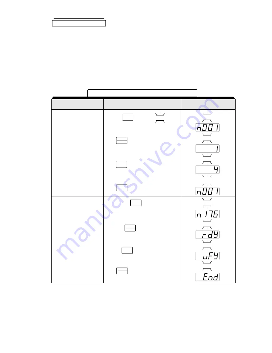
Table 5-7. Verifying Drive Parameters
Set the highest parameter
access level.
This will allow all parameters
to be viewed and set.
Press the
key until the LED
is lit on the digital operator.
DSPL
Execute upload (Copy)
Using Copy Function
Selection (n176)
Press and hold
until n176 is
displayed on the digital operator.
V
PRGM
PRGM
PRGM
PRGM
PRGM
PRGM
PRGM
PRGM
PRGM
Press the
key three times.
V
Then press
.
DATA
ENTER
Press .
DATA
ENTER
Press three
times.
V
Press .
DATA
ENTER
Press . “Vfy” will blink on the display
while verifying.
DATA
ENTER
C.
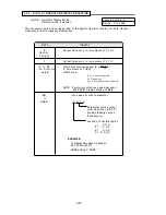
Verify Function (uFy)
Compares the parameter data stored in the operator with the parameter data in the drive. VERIFY
is possible only for drives of the same type (i.e. from one GPD 315/V7 to another), voltage rating,
and control method (V/f or open loop vector).
When the parameters stored in the digital operator match those in the drive, “uFy” will blink in the
display for several seconds, and then "End" will be displayed. When they don’t match “uAE” will be
displayed. Press stop to interrupt the execution of verify, or press Data/Enter to display a list of
parameters that do not match.
5.29 COPY FUNCTION
Summary of Contents for GPD315/V7-4X
Page 1: ...GPD 315 V7 and V7 4X Technical Manual...
Page 4: ......
Page 20: ...xvi...
Page 22: ......
Page 40: ...1 18...
Page 52: ...3 2...
Page 56: ...4 4...
Page 101: ...5 45 PID Block Diagram...
Page 130: ...A1 8...
Page 134: ...A3 2...
Page 136: ...A4 2...
Page 146: ...A6 6...
Page 150: ...A7 4...
Page 154: ...A8 4...
Page 158: ......
Page 160: ......


