PARA-
SETTING RANGE
SETTING
FACTORY
USER
PARA.
METER
NAME
(AND UNITS)
INCREMENT
SETTING
SETTING
REF.
Analog Frequency Reference
n070
Filter Time Constant
0.00 to 2.00
0.01 s
0.10
(CN2, Voltage Ref Input)
n071
Analog Frequency Reference
-255 to 255
1%
100
Gain (CN2, Current Ref Input)
n072
Analog Frequency Reference
-100 to 100
1%
0
5.32
Bias (CN2, Current Ref Input)
Analog Frequency Reference
n073
Filter Time Constant
0.00 to 2.00
0.01 s
0.10
(CN2, Current Ref Input)
n074
Pulse Train Frequency
-255 to 255
1%
100
Reference Gain
n075
Pulse Train Frequency
-100 to 100
1%
0
5.11
Reference Bias
n076
Pulse Train Frequency Ref-
0.00 to 2.00
0.01 s
0.10
erence Filter Time Constant
0:
Multi-Function analog input disabled
1:
Aux. Frequency reference
n077
Multi-Function Analog
2:
Frequency gain
1
0
5.32
Input Selection
3:
Frequency bias
4:
Voltage bias
n078
Multi-Function Analog Input
0:
0 - 10V
1
0
5.32
Signal Selection
1:
4 - 20 mA
n079
Multi-Function Analog Input
0 to 50
1%
10
5.32
Bias Setting
n080
Carrier Frequency
1 to 4 (x 2.5 kHz)
1
3
5.5
7 to 9 (synchronous)
0:
Not Provided
1:
Continuous operation after power
n081
Momentary Power Loss
recovery within 2 sec.
Ride-through Method
2:
Continuous operation after power
1
0
5.16
recovery within control logic time
(no fault output)
n082
Number of auto restarts
0 to 10
1
0
attempts
n083
Prohibit Frequency 1
0.00 to 400.0
0.01 (Hz)
0.00
or 0.1 (Hz)
n084
Prohibit Frequency 2
0.00 to 400.0
0.01 (Hz)
0.00
5.6
or 0.1 (Hz)
n085
Prohibit Frequency 3
0.00 to 400.0
0.01 (Hz)
0.00
or 0.1 (Hz)
n086
Prohibit Frequency Deadband 0.00 to 25.50
0.01 (Hz)
0.00
n089
DC Injection Current
0 to 100
1 (%)
50
n090
DC Injection Time at stop
0.0 to 25.5
0.1 (sec)
0.5
5.7
n091
DC Injection Time at start
0.0 to 25.5
0.1 (sec)
0.0
n092
Stall Prevention During
0:
Enabled
1
0
Deceleration
1:
Disabled
n093
Stall Prevention During
30 to 200
1 (%)
170
5.23
Acceleration
n094
Stall Prevention Level During
30 to 200
1 (%)
160
Running
n095
Frequency Detection Level
0.00 to 400.0
0.01 (Hz)
0.00
5.19
or 0.1 (Hz)
A1-4
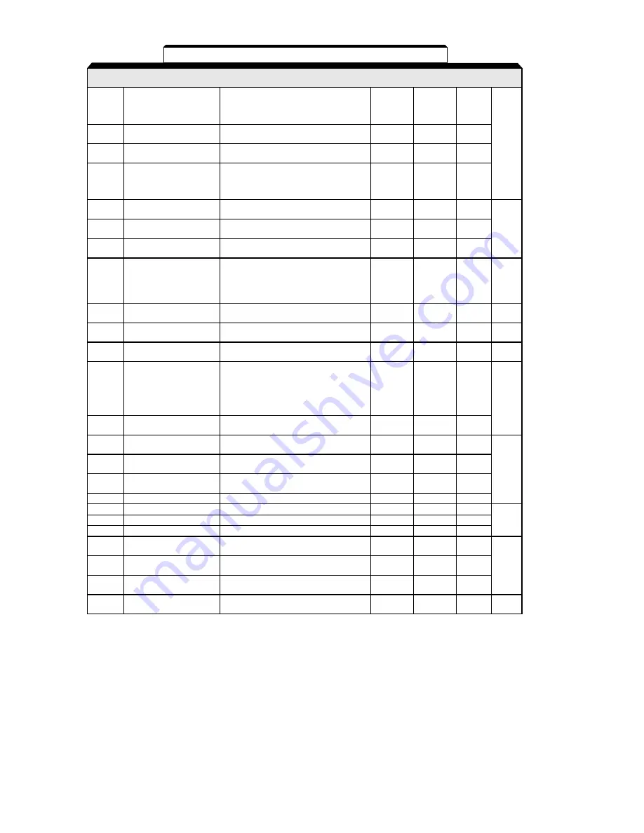
Table A1-1. Drive Parameters - Continued
Summary of Contents for GPD315/V7-4X
Page 1: ...GPD 315 V7 and V7 4X Technical Manual...
Page 4: ......
Page 20: ...xvi...
Page 22: ......
Page 40: ...1 18...
Page 52: ...3 2...
Page 56: ...4 4...
Page 101: ...5 45 PID Block Diagram...
Page 130: ...A1 8...
Page 134: ...A3 2...
Page 136: ...A4 2...
Page 146: ...A6 6...
Page 150: ...A7 4...
Page 154: ...A8 4...
Page 158: ......
Page 160: ......


