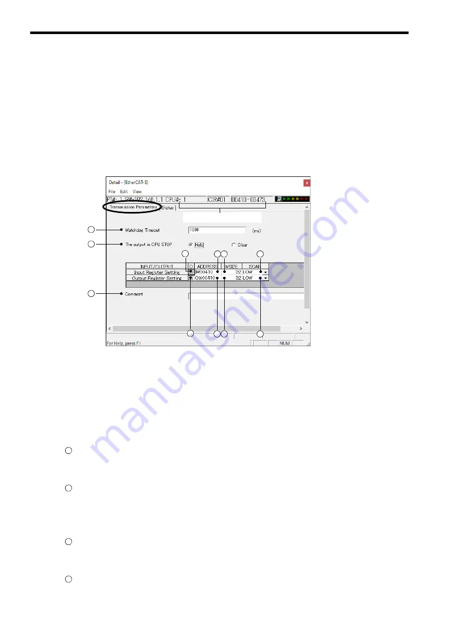
4.2 EtherCAT Detail Definition
4.2.1 Transmission Parameters Tab Page
4-4
4.2 EtherCAT Detail Definition
The
EtherCAT Detail Definition
window has two tab pages, namely Transmission Parameters and Status. Select the
appropriate tab page to perform setting and monitoring.
4.2.1 Transmission Parameters Tab Page
On the Transmission Parameters tab page, set the network parameters required to perform EtherCAT communication.
The following explains the details of the network parameter setting.
After changing the setting on the Transmission Parameters tab page, save the definition data by selecting
File -
Write
from the main menu.
Configuration Information
Displays the 264IF-01 Module configuration information. The configuration information is the same as the information
displayed in the
Module Details
area in the
Module Configuration
window.
RACK#:
The rack number of the rack in which the 264IF-01 Module is defined.
Slot#:
The slot number of the slot in which the 264IF-01 Module is defined.
CIR#:
The circuit number of the EtherCAT port on the 264IF-01 Module.
Parameters
Watchdog Timeout
Set the monitoring time for detecting an error in EtherCAT communication.
The setting range is 0 to 65535. (This setting is for future use. Making a setting has no effect.)
The output in CPU STOP
Set the status of the output data when the STOP status has been set at the controller CPU.
If
Hold
is set, the last data before the STOP status is output. If
Clear
is set, 0 data is output.
Input Register Setting
D
Set whether or not the controller CPU exchanges input data with EtherCAT.
When the checkbox is checked, there is no exchange of data.
ADDRESS
Set, as a hexadecimal word, the initial address of the input area of the controller CPU for the output data of the
EtherCAT master device. The setting range is 0 to 7FFF.
1
2
4 5
Configuration Information
6
7
8 9
10
11
3
1
2
3
4


