


7-36
-
+
ELEC
EAS00798
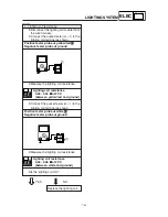
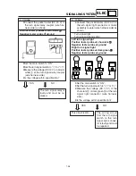
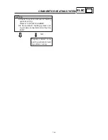
2.
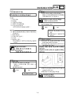
The tail/brake light fails to come on.
1. Tail/brake light bulb and socket
8
Check the tail/brake light bulb and socket
for continuity.
Refer to “CHECKING THE BULBS AND
BULB SOCKETS”
8
Are the tail/brake light bulb and socket
OK?
YES
NO
Replace the tail/brake
light bulb, socket or
both.
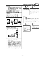
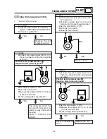
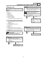
3. Voltage
8
Connect the pocket tester (DC 20 V) to
the tail/brake light coupler (wire harness
side) as shown.
Positive tester probe
J
J
J
J
J
green/ yellow
1
1
1
1
1
Negative tester probe
J
J
J
J
J
black
2
2
2
2
2
8
Set the main switch to “ON”.
8
Pull in the brake levers.
8
Measure the voltage (DC 12 V) of yel-
low green/yellow
1
on the tail/brake light
coupler (wire harness side).
8
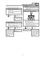
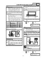
Is the voltage within specification?
YES
NO
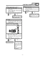
2. Brake light switches
8
Check the brake light switches for conti-
nuity.
Refer to “CHECKING THE SWITCHES”.
8
Is the brake light switch OK?
YES
NO
Replace the brake
light switch.
The wiring circuit from
the main switch to the
tail/brake light bulb
connector is faulty
and must be repaired.
Refer to “CIRCUIT
DIAGRAM”.
The wiring circuit
from the main switch
to the tail/brake light
coupler is faulty and
must be repaired.
Refer to “CIRCUIT
DIAGRAM”.
This circuit is OK.
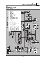
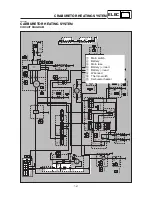
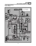
SIGNALING SYSTEM
B
G/Y
1
2
Y
L
L
B