


ELEC
LIGHTING SYSTEM
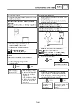
2. The tail/brake light fails to come on.
7-30
• Set the main switch to "ON"
• Measure the voltage (DC 12 V) of blue
1
on the brake light coupler (wire harness).
• Is the voltage within specification?
• Check the tail/brake light bulb and socket
for continuity.
Refer to “CHECKING THE BULBS AND
BULB SOCKETS”
• Are the tail/brake light bulb and socket OK?
YES
NO
YES
NO
1. Tail/brake light bulb and socket
Replace the tail/brake
light bulb, socket or
both.
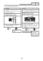
2. Voltage
• Connect the pocket tester (DC 20 V) to the
tail light coupler (wire harness), as shown.
Positive tester probe --> blue
1
Negative tester probe -->black
2
The circuit is OK.
The wiring circuit from
the main switch to the
meter assembly
coupler is faulty and
must be repaired.
Y L
Y
L
B
Ch
Dg
21/5W
2
1
•
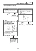
Set the main switch to ‘ON‘
•
Measure the voltage (DC 12V) of blue/red
1
on the auxiliary light coupler (wire
harness).
•
Is the voltage within specification?
•
Check the auxiliary light bulb and socket
for continuity.
Refer to “CHECKING THE BULB AND
BULB SOCKETS”.
•
Are the auxiliary light bulb and socket OK?
YES
NO
YES
NO
1. Auxiliary light bulb and socket.
Replace the auxiliary
light bulb, socket, or
both.
2. Voltage
•
Connect the pocket tester (DC 20 V) to
the auxiliary light coupler (wire harness),
as shown.
Positive tester probe --> blue/red
1
Negative tester probe -->black
2
The circuit is OK.
The wiring circuit from
the main switch to the
auxiliary light coupler
is faulty and must be
repaired.
3. The auxiliary light fails to come on.
Summary of Contents for YBR250 2007
Page 1: ...YBR250 SERVICE MANUAL 5D1 F8197 E0 2007 ...
Page 2: ......
Page 359: ...YAMAHA MOTOR DA AMAZÔNIA LTDA ...


