background image

TX6n/5n/4n  Reference Manual

23

Panel Operations

Setting the Lock

1.

Use encoder A to move the cursor to the lock that you want to set, and use encoder B to change the setting.

The parameter you switched will blink.

2.

Press the [ENTER] button. The lock will be applied.

Temporarily defeating panel lock

Here’s how you can temporarily defeat the panel lock. Even if the lock is temporarily defeated, it will again be set the next time 
the power is turned on.

• If you want to clear panel lock, defeat the lock as explained below, and then set Panel to Normal.

1.

Simultaneously hold down the [HOME] button and [EXIT] button for at least three seconds.

A message of “Unlock panel” will appear.

2.

Press the [ENTER] button.

Panel lock will be temporarily (until the power is turned on again) defeated.

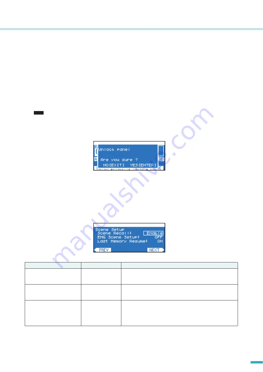
Scene Setup

Here you can make settings related to scene recall.

Parameter name

Range

Explanation

Scene Recall

Enable/Disable

Specifies whether scene recall via front panel operations will be 
allowed. This will not affect control from an external device such as Amp 
Editor.

EMG Scene Setup

OFF, 00–49

Specifies the scene number that will be recalled when the EMG (Emer-
gency) signal is received from an external controller. If this is OFF, a 
scene will not be recalled even if an EMG signal is received.

Last Memory Resume

ON/OFF

Specifies what will happen when the power is turned on. If this is ON, 
the unit will start up with the settings that were in effect when the power 
was last turned off. If this is OFF, the unit will start up by recalling the 
scene of the scene number that was being used when the power was 
last turned off.

NOTE

Summary of Contents for TX4n

Page 1: ...Reference Manual EN ...

Page 2: ... 35 X Over Speaker Processor 36 Output Delay Speaker Processor 37 6Band Output EQ Speaker Processor 37 Output Level Speaker Processor 38 Mute On Off Speaker Processor 38 Limiter Speaker Processor 39 Output Router 39 SCENE Screen 40 Recalling a scene 40 Storing a scene 41 Editing a scene 42 Erasing a scene Clear 42 Initializing the internal memory 43 System Connection Examples 44 Daisy chain connec...

Page 3: ...In order to view the downloaded manuals Adobe Reader must be installed in your computer If you don t have Adobe Reader please access the Adobe Corporation s website at the following URL and download Adobe Reader free of charge http www adobe com Setup For details on setting up the TXn and Amp Editor refer to the TX6n 5n 4n Owner s Manual and Amp Editor Owner s Manual TX6n 5n 4n Owner s Manual prin...

Page 4: ...udio signal processing functionality provided by the internal DSP Components organized into modules accord ing to their functionality are placed in the signal path Component These are modules in the signal path that organize audio signal processing according to their functionality Library The settings of all Speaker Processor components can be saved together in a library A library can be saved onl...

Page 5: ...nds or longer or switch the mode from the MENU screen General Sensitivity Amp Gain or Amp Editor s Detail View window Standby is a state in which the speaker output s power amp section is off operation other than speaker output will con tinue e IDENTIFY indicator When you click the Identify button in the Tree View window of Amp Editor the IDENTIFY indicator of the correspond ing amplifier will bli...

Page 6: ...essed y BRIDGE indicator This will light green if the amplifier mode is set to Bridge u PARALLEL indicator This will light orange if the amplifier mode is set to Parallel i MUTE indicator This indicator will light red if muting is turned on by the MUTE button or from Amp Editor When the power is turned on the output signal will also be muted and the indicator will blink red until audio begins bein...

Page 7: ... you can move to the screen of the next highest level To temporarily disable panel lock simultaneously hold down the HOME button and EXIT button for three seconds or longer If you hold down this button for three seconds or longer in the HOME screen the FAULT OUTPUT connector output will be reset NC and C will be connected 8 ENTER button Use this to select a parameter or to finalize an edited param...

Page 8: ...s turned off this connector will output the input signal without any change page 44 However internal settings will be switched when the power is switched on off causing the output signal to be muted for an instant If desired you can remove the AES IO card and install a separately sold MY card For details on the types of MY card that can be used and how to install them refer to Optional I O cards p...

Page 9: ...outlet used is earthed grounded this device will be properly earthed as well Also grounding the screw sometimes reduces hum and interference noise Supported I O cards You can remove the AES IO card from the TXn s rear panel and install a separately sold MY mini YGDAI card As of Sep tember 2009 the following MY cards are supported For the latest information refer to theYamaha pro audio website http...

Page 10: ... the card to be installed with the guide rails inside the slot and insert the card into the slot Push the card all the way into the slot so that the contacts of the card are correctly mated with the connector inside the slot 4 Fasten the card using the screws attached to the card Be aware that malfunctions or faulty operation may occur if the card is not fastened You must turn off the amplifier s ...

Page 11: ...the two screws that fasten the front filter grill and remove the grill 4 Remove the filter element and wash it in plain water If the filter element is exceptionally dirty mild deter gent may be used 5 Dry the filter element completely Never replace the filter element while it is still wet 6 Replace the filter element on the air intake hook the front filter grill on the amplifier and secure it usin...

Page 12: ...n press the ENTER button when you finish editing If you move to a differ ent screen without pressing the ENTER button your change will not be applied Adjusting the Attenuation When the display shows the attenuator i e in the HOME screen or the METER screen you can use encoders A and B to adjust each channel s attenuation If the display shows a screen other than the HOME screen or METER screen enco...

Page 13: ...ut Signal Chain Slot Input Signal Chain Output Signal Chain Input Router Input On Off 4x4 Matrix Mixer 8Band Input EQ Input Delay Oscillator Mix Speaker Processor Output Router ANA INPUT VOLTAGE SLOT INPUT VOLTAGE SP OUTPUT VOLTAGE SP OUTPUT POWER SP OUTPUT IMPEDANCE SLOT OUTPUT METER THERMAL X Over Input Level X Over Polarity X Over Output Delay 6Band Output EQ Output Level Mute On Off Limiter RE...

Page 14: ...p Makes scene settings Misc Setup Sets the amplifier s internal clock etc MENU page 24 General Sensitivity Amp Gain Sets the input sensitivity gain Stereo Bridge Parallel Specifies the amplifier s mode Stereo Bridge Parallel Attenuation Link Specifies whether attenuator operation will be linked between channels A and B Input Redundancy Specifies the redundant connection mode etc Signal Path Makes ...

Page 15: ...nuation This screen will appear imme diately after you power on the amplifier You can also access it by pressing the HOME button or by pressing the EXIT button several times You can also move from this screen to various other screens As a shortcut from the HOME screen you can hold down one of the following buttons for three or one seconds or longer to execute the corresponding function page 7 HOME...

Page 16: ...slot exceeds the maximum value of digital signal the top segment of the meter will light w Gain This indicates the currently specified gain for each channel The gain can be adjusted in the MENU screen page 24 e Attenuation This indicates the current attenuation for each channel You can use encoders A B to adjust the attenuation for each channel Meter types that can be shown The display units can b...

Page 17: ...he screen for the meter whose settings you want to change 3 Press the second from right function button SETTING to access the SETTING screen for that meter 4 Press the second from left function button CH A B or CH 1 2 to access the settings for the channel that you want to edit 5 Use encoder A to move the cursor to the parameter that you want to edit and encoder B to edit the parameter value The e...

Page 18: ... number of times Detect Count within the specified duration Detect Time Detection is in 2 ms intervals Alert Min TH Specifies the lower threshold value for the alert Alert Max TH Specifies the upper threshold value for the alert Detect Time 1 10s Specifies the time during which points exceeding the threshold value will be counted Detect Count 1 100 Specifies the number of times that a point exceed...

Page 19: ... the parameter value is blinking press the ENTER button to confirm the value Non blinking parameter values are reflected by the amplifier in real time Device Setup Here you can specify identifiers for distinguishing the amplifier on a network You can also access this screen from the HOME screen by holding down the ENTER button for three seconds or longer UTILITY Screen Parameter name Range Explana...

Page 20: ...ock will automatically be switched according to the following order of priority 1 The selected port of the slot 2 The internal word clock For some types of installed I O card e g for an AD card Auto Scan Mode will not operate even if this setting is ON Refer to Supported I O cards page 9 to check if your I O card supports Auto Scan Mode If two TXn amplifiers are bi directionally connected via a di...

Page 21: ...Slot Indicates the name of the card installed in the slot By default an AES IO card is installed Parameter name Range Explanation IP Address Mode DHCP Manual Specifies whether the IP address will be set automatically from Amp Editor or the DHCP server DHCP or set manually Manual IP Address 001 000 000 001 223 255 255 254 Indicates the IP address for Auto mode Specifies the IP address for Manual mo...

Page 22: ...annot be changed from the front panel Only display related operations can be performed Full Lock The front panel will be inoperable w MUTE Key This locks mute operations by the MUTE button This can be set only if the Panel setting is Normal e Att Dial This locks attenuation adjustments by the A B encoders This can be set only if the Panel setting is Normal Parameter name Range Explanation Contrast...

Page 23: ...l lock will be temporarily until the power is turned on again defeated Scene Setup Here you can make settings related to scene recall Parameter name Range Explanation Scene Recall Enable Disable Specifies whether scene recall via front panel operations will be allowed This will not affect control from an external device such as Amp Editor EMG Scene Setup OFF 00 49 Specifies the scene number that w...

Page 24: ...U screen 2 Use encoder A or B to select the sub category that you want to edit and press the ENTER button to access the screen for that sub category Parameter name Range Explanation Clock Day Month Year Hour Minute Sets the amplifier s internal clock This is used when recording the event log If daylight saving time has been enabled from Amp Editor DST will appear before the day This can be set at ...

Page 25: ...he settable range will differ for each model The gain and input sensitivity are linked you may edit either one Gain Mode Link ON OFF Specifies whether the gain and input sensitivity settings will be linked between channels Standby On Standby On Switches the power between Standby and On modes Standby is a state in which the speaker output s power amp section is off operation other than speaker outp...

Page 26: ...e enabled when the interrupted slot input has recovered When using Override mode this specifies whether the slot input will be re enabled when the analog input is interrupted Ovrrid Ch Link ON OFF When using Override mode this specifies whether both channels will switch together ON or separately OFF when analog input is detected as being present or absent Ovrrid Thrsld 30 0 0 0 dBFS When using Ove...

Page 27: ...not be detected appropriately Notch On ON OFF Enables disables the notch filter that eliminates the frequency component of the pilot tone so that the pilot tone will not be output by the amplifier Notch Q 0 10 63 0 Specifies the width of the notch filter s frequency band Detected Lvl Indicates the level of the detected pilot tone Parameter name Range Explanation Frequency Type 5 Hz 20 kHz 10 Hz 20...

Page 28: ...n of Start and Apply the parameters listed below are displayed and edited separately for the high frequency component High and low frequency component Low Enable ON OFF Turns pilot tone output on off Calibration Start Start Starts detection of level and impedance Detected Lvl Indicates the detected level Detected Imp Indicates the detected impedance value Apply Apply Based on the detected level an...

Page 29: ...k 1 100 ms Specifies the time over which 20 dB of attenuation will be applied after the threshold value is exceeded Release 0 01 10 00 s Specifies the time over which the voltage that had been attenuated will be returned to the original level after falling back to below the threshold value Parameter name Range Explanation On ON OFF Turns the power limiter on off Threshold TX6n 10 4800 W TX5n 10 42...

Page 30: ...h window allows you to view and edit the signal route and functions in a more graphical manner SIGNAL PATH Block Diagrams SIGNAL PATH Screen NOTE Redundancy Gain Sens Analog Input A Analog Input B Speaker Output B Speaker Processor Speaker Processor Speaker Output A ADC Matrix Mixer Slot Input Router Gain 1 2 Pol Pol Pol Pol PEQ PEQ Delay Delay OSC OSC X Over Level Pol Level Pol Delay PEQ Level MU...

Page 31: ...mponent If you selected SP Proc Speaker Processor use encoder A or B to select the component you want to edit and press the ENTER button to access the screen for that component 4 Press the second or third from left function button to access the settings for the parameter such as CH A B or SL CH 1 2 that you want to edit 5 Use encoder A to move the cursor to the parameter that you want to edit and ...

Page 32: ...r the DME series or SP2060 by Amp Editor and use them 1 In the SIGNAL PATH screen use encoder A or B to select SP Proc Speaker Processor and press the ENTER button to access the Speaker Processor screen 2 Press the right most function button LIB to access the library screen 3 Use encoder A or B to select the settings that you want to recall 4 Press the second from left function button CH A B to sw...

Page 33: ...ixer This is a 4 input 4 output mixer with the input channels and output channels arranged in a matrix Parameter name Range Explanation Input Assign Slot Ch1 Slot Ch16 Specifies the routing from the slot input to each input channel Input Gain 24 0 dB 24 0 dB Specifies the gain from the slot input to each input channel Parameter name Range Explanation In Polarity NORMAL INVERTED Specifies phase rev...

Page 34: ...ilter type You cannot select the type for frequency bands other than the first and last B G They are fixed at PEQ For details on the filter types refer to page 38 Q 63 0 0 10 Specifies the width of each frequency band Frequency 20 0 Hz 20 0 kHz Specifies the center frequency of each frequency band Gain 18 0 18 0 dB Specifies the gain for each frequency band Bypass ON OFF Turns bypass on off for ea...

Page 35: ...OFF Switches on off the input from the Input Delay to the mix point before the Speaker Processor Osc To SP ON OFF Switches on off the input from the oscillator to the mix point before the Speaker Processor Osc On ON OFF Turns the oscillator on off Osc Level 0 00 dB Specifies the output signal level Wave Form SINE100 Hz SINE1 kHz SINE10 kHz PINK BURST Vari Selects the waveform that will be generate...

Page 36: ...e and the filter type for the low pass filter If you select Thru the filter will not be applied AdjGc Adjustable Gain Control But Butterworth Bessl Bessel L R Linkwitz Riley LPF Gc 6 6 dB Specifies the gain at the cutoff frequency when Type is set to AdjGc HPF Freq 20 0 Hz 20 0 kHz Specifies the cutoff frequency of the high pass filter HPF Type Thru 6 dB Oct 12 dB AdjGc 12 dB But 12 dB Bessl 12 dB...

Page 37: ...xplanation On ON OFF Turns the delay on off Delay Time 0 00 500 00 ms Specifies the delay time Parameter name Range Explanation Type PEQ L SHELF 6 L SHELF 12 H SHELF 6 H SHELF 12 HPF LPF APF 1st APF 2nd Horn EQ Selects the filter type Q 63 0 0 10 Specifies the width of each frequency band Frequency 20 0 Hz 20 0 kHz Specifies the center frequency of each frequency band Gain 18 0 18 0 dB Specifies t...

Page 38: ...the lower frequencies LPF Low Pass Filter A gently 12 dB Oct diminishing curve will be applied to the higher frequencies APF All Pass Filter This filter modifies only the phase passing the signal at all frequencies This is used to correct the phase at the crossover band APF 1st will invert the phase 0 180 and APF 2nd will invert the phase 0 360 For APF 2nd you can adjust the Q setting Horn EQ CD C...

Page 39: ...cording to the HPF cutoff frequency of Speaker Processor s Crossover Fast 1 4 wavelength of cutoff frequency Mid 1 2 wavelength of cutoff frequency Slow 1 wavelength of cutoff frequency Attack 0 0 120 0 ms Specifies the attack time when Manual mode is selected Release Mode Fast Mid Slow Manual Selects the release speed of the limiter If the Manual setting is selected use the Release setting below ...

Page 40: ...e recalled when an EMG signal is received from an external controller page 23 For the current scene the scene number will be highlighted Recalling a scene Here s how to recall the desired scene 00 49 from the scene list 1 In the HOME screen press the right most function button SCENE to access the SCENE screen 2 Use encoder A to select the scene number that you want to recall 3 Press the left most ...

Page 41: ...encoder A to move the cursor to the scene name and turn encoder B to access the screen where you can specify the scene name 5 Specify the scene name by using encoder A to move the cursor location and using encoder B to select the desired characters You can also use the function buttons to insert a character at the cursor location INS or to delete a character DEL 6 When you ve finished specifying t...

Page 42: ...press the ENTER button to execute your edits page 41 Erasing a scene Clear Here s how to clear a scene 01 49 However you cannot clear the current scene 1 In the HOME screen press the right most function button SCENE to access the SCENE screen 2 Use encoder A to select the scene number that you want to clear 3 Press the right most function button CLEAR The Scene Clear confirmation screen will appea...

Page 43: ...n internal memory up to that point will be lost Use caution when performing the following steps 1 Power off the TXn 2 While holding down the HOME button turn on the power the Initialize screen will appear 3 Use encoder A to select the data that you want to initialize and press the ENTER button to execute the Ini tialize operation When initialization is completed the amplifier will automatically re...

Page 44: ...ith processing applied In order to monitor and control the amplifiers from Amp Editor use Ethernet cables to connect the computer to each amplifier This allows you to monitor and control all of the amps in the workspace from a single computer In the case of digital connections you ll need to make word clock settings page 20 Specify whether you want the slot s CH 1 2 to be the master clock or turn ...

Page 45: ...same XLR con nector as for analog connections is used take care not to inadvertently connect a digital signal and analog signal A high quality 110Ω digital cable can be extended to approximately 100 meters when operating at 96 kHz theoretically to approximately 200 meters when operating at 48 kHz However this length cannot be guaranteed in some cases due to dif ferences in cable quality and the nu...

Page 46: ...ection the system will switch to the analog audio signal In order to enable a redundant connection you ll need to access the MENU screen General Input Redun dancy and choose Backup so that the digital audio signal has priority page 26 Redundant connections Backup Network switch Amp control TXn Amp Editor Computer Amp control Amp control Amp control TXn TXn Mixer THRU OUT IN THRU OUT IN IN Analog a...

Page 47: ...r to make EtherSound settings However on the amplifiers the amplifier control connections and EtherSound network connections are separate You can connect up to three MY16 EX I O expansion cards to a single MY16 ES64 card EtherSound connections NOTE Network switch Amp control TXn Amp Editor AVS ESMonitor Computer Amp control Amp control Amp control TXn TXn IN EtherSound EtherSound EtherSound networ...

Page 48: ... ES to make a bridge connection from an EtherSound network to an AES EBU signal Bridge connections from EtherSound to AES EBU Network switch Amp control TXn Amp Editor AVS ESMonitor Computer Amp control Amp control Amp control TXn TXn IN EtherSound EtherSound network NAI48 ES EtherSound IN IN AES EBU AES EBU AES EBU ...

Page 49: ... the amplifiers and make CobraNet settings for the MY16 CII card However on the amplifiers the connections for amplifier control from Amp Editor and the connections for CobraNet are separate CobraNet connections Network switch Amp control Amp Editor Computer Amp control Amp control Amp control TXn TXn IN CobraNet network CobraNet IN IN Network switch TXn CobraNet CobraNet MY16 CII MY16 CII MY16 CI...

Page 50: ...uch as the NHB32 C to make a bridge connection from a CobraNet net work to an AES EBU signal Bridge connections from CobraNet to AES EBU Network switch Amp control TXn Amp Editor Computer Amp control Amp control Amp control TXn TXn IN CobraNet network NHB32 C IN IN AES EBU AES EBU CobraNet AES EBU ...

Page 51: ...r is a relay circuit and oper ates as follows The relay contacts used in the FAULT OUTPUT connector are rated for a load of 1A DC 30V Do not apply a load that exceeds this rating Use Amp Editor to make settings for the FAULT OUTPUT connector Euroblock plugs are used for the FAULT OUTPUT connector Euroblock connection methods are described in Euroblock plug connection page 52 in this manual In Amp ...

Page 52: ...n and use stranded wire to make connections With a Euroblock connection the stranded wire may be prone to breakage because of metal fatigue due to the weight of the cable or due to vibration When rack mount ing your equipment use a lacing bar when possible to bundle and fasten the cables If cables will be frequently connected and disconnected as in the case of a portable installation we recommend ...

Page 53: ...u TX6n TX5n Tx4n 28 0 15 8 14 4 13 2 28 1 15 7 14 3 13 1 28 2 15 6 14 2 13 0 28 3 15 5 14 1 12 9 28 4 15 4 14 0 12 8 28 5 15 3 13 9 12 7 28 6 15 2 13 8 12 6 28 7 15 1 13 7 12 5 28 8 15 0 13 6 12 4 28 9 14 9 13 5 12 3 29 0 14 8 13 4 12 2 29 1 14 7 13 3 12 1 29 2 14 6 13 2 12 0 29 3 14 5 13 1 11 9 29 4 14 4 13 0 11 8 29 5 14 3 12 9 11 7 29 6 14 2 12 8 11 6 29 7 14 1 12 7 11 5 29 8 14 0 12 6 11 4 29 ...

Page 54: ...In this case the maximum output will differ depending on the model meaning that as you raise the input level the power amp section of the TX5n and TX4n will clip earlier than the TX6n Conversely if you want to obtain the maximum output power W from the amplifiers for a given maximum input level set the input sensitivity to match the maximum input level In this case the output level for a given inp...

Page 55: ...ge is shown Cannot edit while online Settings cannot be edited because the unit is online with Amp Editor File writing Do not turn off A file is being written to internal memory Never turn off the power while this message is shown Calibrating EXIT to cancel Calibration is being executed If you decide to cancel calibration press the EXIT button Initializing Do not turn off Internal memory is being ...

Page 56: ... may have run down Contact your Yamaha dealer Fan failed Ch The channel cooling fan has stopped Check whether dirt or a foreign object could have clogged the fan and clean the fan appropriately If this does not solve the problem it is likely that the device has malfunctioned Immediately stop using the unit and contact your Yamaha dealer DC detected Since a direct current component was detected in ...

Page 57: ...igital input signal from the same sound source but differing latencies are being mixed via the 4x4 Matrix Mixer If you re using redundant connections set the MENU screen General Input Redundancy Mode setting to Backup Alter natively change the settings of the 4x4 Matrix Mixer etc to turn off one of the signals An alert message is displayed An amplifier malfunction or other alert event related to t...

Page 58: ...rog Source 28 Calibration 28 Card 9 CLIP indicator 6 Clock 24 CobraNet connections 49 Component 4 Crestron 51 Crossover 36 D Daisy chain connection 44 Delay 34 37 Device ID 4 19 Device Setup 19 Digital input output connectors I O card slot 8 Display 7 E EMG Scene Setup 23 Encoders A B 7 ENTER button 7 Equalizer 34 37 EtherSound connections 47 Euroblock plug 52 EXIT button 7 External controllers 51...

Page 59: ... 29 POWER switch and indicator 5 PROTECTION indicator 6 R Redundant connections 46 Remote control 51 S Scene 4 40 Scene Recall 23 Scene screen 40 Scene Setup 23 Screen categories 14 Screen structures 13 Screw holes for handles 7 Sensitivity 25 53 54 Sensitivity Amp Gain 25 Serial No 21 SETTING screen 17 Setup 3 Signal Chain 27 SIGNAL indicator 6 SIGNAL PATH screen 4 30 Slot Input Router 33 Slot In...

Page 60: ...U R G Pro Audio Digital Musical Instrument Division Yamaha Corporation 2009 Yamaha Corporation 909 PO D0 ...

Reviews: