


–49–
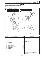
CYLINDER HEAD AND CYLINDER
ENG
Order
Job name / Part name
Q’ty
Remarks
1
2
3
4
5
6
7
8
9
10
11
12
13
14
15
Cylinder head and cylinder removal
Spark plugs
Cylinder head
Gasket
Cylinders
Gasket
Intake manifolds
Spacers
Reed valve seats
Reed valve stoppers
Reed valves
Gaskets
Piston rings
Piston pins
Pistons
Bearings
2
1
1
2
1
2
2
2
4
4
2
4
2
2
2
Remove the parts in the order below.
Make sure its projection comes to the
exhaust side.
For installation, reverse the removal
procedure.
10 Nm (1.0 m
kg, 7.2 ft
lb)
A :
13 Nm (1.3 m
kg, 9.4 ft
lb)
1st
2nd
23 Nm (2.3 m
kg, 17 ft
lb)
B
:
20 Nm (2.0 m
kg, 14 ft
lb)
C :
13 Nm (1.3 m
kg, 9.4 ft
lb)
D :
ENGINE
CYLINDER HEAD AND CYLINDER
500
Summary of Contents for SX500D
Page 1: ...SUPPLEMENTARY SERVICE MANUAL ...
Page 85: ... 81 CABLE ROUTING SPEC CABLE ROUTING 500 ...
Page 87: ... 83 CABLE ROUTING SPEC ...
Page 89: ... 85 CABLE ROUTING SPEC ...
Page 91: ... 87 CABLE ROUTING SPEC ...
Page 93: ... 89 CABLE ROUTING SPEC ...
Page 95: ... 91 CABLE ROUTING SPEC ...
Page 97: ... 93 CABLE ROUTING SPEC CABLE ROUTING 600 700 ...
Page 99: ... 95 CABLE ROUTING SPEC ...
Page 101: ... 97 CABLE ROUTING SPEC ...
Page 103: ... 99 CABLE ROUTING SPEC ...
Page 105: ... 101 CABLE ROUTING SPEC ...
Page 107: ... 103 CABLE ROUTING SPEC ...
Page 109: ... 105 CABLE ROUTING SPEC ...
Page 112: ...WIRING DIAGRAM ...
Page 114: ...WIRING DIAGRAM ...


