background image

Checking the Battery

91

ProMix 01 User’s Guide

1. Press [UTILITY].

The UTILITY menu appears.

2. Select BATTERY CHECK and 

press [ENTER].

The BATTERY CHECK LCD 
function appears. 

3. To exit this function and 

return to the UTILITY menu, 
select EXIT and press 
[ENTER], or just press [UTIL-
ITY].

The UTILITY menu reappears.

Checking the Battery

ProMix 01 uses a long-life battery to backup its RAM memory. The 
battery should last for up to five years, and you can check its condition 
using the BATTERY CHECK function. 

If the BATTERY CHECK function indicates that the battery needs 
replacing, please contact your Yamaha dealer. 

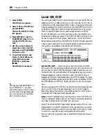
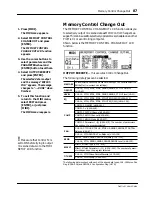
Shown below is the BATTERY CHECK LCD function. 

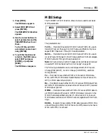
Possible messages are:

Battery is OK!!

 — battery is OK.

Warning! Low battery

 — battery power is getting low. Ask your 

Yamaha dealer to install a new battery. 

Warning! No battery

 — no battery is installed. Ask your Yamaha 

dealer to install a new battery.

Important: 

Do not try to replace the battery yourself.

Summary of Contents for Programmable Mixer 01

Page 1: ...00 5 SEL ON 6 6 0 5 10 20 40 60 00 6 SEL ON 7 6 0 5 10 20 40 60 00 7 SEL ON 8 6 0 5 10 20 40 60 00 8 SEL ON 9 6 0 5 10 20 40 60 00 9 SEL ON 10 6 0 5 10 20 40 60 00 10 SEL ON 11 6 0 5 10 20 40 60 00 11...

Page 2: ...cate either this product or the device that is being affected by the interference Utilize power outlets that are on different branch circuit breaker of fuse circuits or install AC line filter s In the...

Page 3: ...r Interface 11 3 Mixer Functions 17 4 Auxiliaries and Effects 29 5 CUE 49 6 Groups and Pairs 55 7 Scene Memories 61 8 Dynamics Processors 67 9 MIDI 79 10 Other Functions 89 Troubleshooting 93 Appendix...

Page 4: ...ii ProMix 01 User s Guide...

Page 5: ...ctions 17 Phantom Power 18 Pad 18 Gain 18 Metering 19 Phase 20 EQ 21 EQ Library 22 EQ Presets 23 Faders 25 ON Buttons 25 Pan and Balance 26 Stereo Output Balance 26 Stereo Pair Pans 27 Stereo Width 27...

Page 6: ...rs 56 Listening to Groups 56 Group Block Diagram 57 Pairing Channels 58 Pair Block Diagram 59 7 Scene Memories 61 What are Scene Memories 62 What s Stored in a Scene Memory 62 What is the Edit Buffer...

Page 7: ...95 LCD Function Map 96 Button Protector 97 Data Types 98 Error Messages 100 ProMix 01 Compatible Products 104 General Specifications 105 Input Specifications 106 Output Specifications 106 Digital OUT...

Page 8: ...User s Guide MIDI Data Format Add 16 1 General Items Add 16 2 Transmission Reception Add 16 3 Transmission Condition Add 18 4 Receive Condition Add 18 5 Bulk Dump Request Format Add 19 Button Number...

Page 9: ...Touring ProMix 01 1 ProMix 01 User s Guide 1 Touring ProMix 01 In this chapter Top Panel 2 Rear Panel 5 ProMix 01 Block Diagram 8 An Analog Mixer Analogy 9...

Page 10: ...40 60 00 3 SEL ON 4 6 0 5 10 20 40 60 00 4 SEL ON 5 6 0 5 10 20 40 60 00 5 SEL ON 6 6 0 5 10 20 40 60 00 6 SEL ON 7 6 0 5 10 20 40 60 00 7 SEL ON 8 6 0 5 10 20 40 60 00 8 SEL ON 9 6 0 5 10 20 40 60 00...

Page 11: ...our options The currently selected RTN SEND channel is indicated by the highlighted arrow at the right side of the LCD When a channel is selected its SEL button LED lights up 7 ON buttons These button...

Page 12: ...angle 13 ENTER button The exact operation of this button depends on the selected LCD func tion Essentially it performs two operations First to enter confirm settings made using the PARAMETER wheel Se...

Page 13: ...to the CUE 2TR IN switch and are monitored via the monitor out and headphones The outputs of a 2 track master recorder can be connected here for confidence mon itoring and playback 3 ST IN These are u...

Page 14: ...es can be connected here for monitoring The phones output signal sourceisthesameasthatof themonitoroutput Theheadphonelevel is set using the PHONES LEVEL control 7 MONITOR OUT These are unbalanced 1 4...

Page 15: ...onnect ProMix 01 to your home hi fi system TheDIGITALCOAXIALoutputisanRCA phonojack Itoutputsthe main stereo signals for recording and can be connected to DAT MD and DCC digital recorders via a 75 ohm...

Page 16: ...COAXIAL ANALOG 10dB UNBAL R L R L PHANTOM MASTER 48V ON OFF ON ON 2TR IN 10dB UNBAL R L R L ODD L OUT EVEN R OUT METER 3BAND PEQ COMP AD 3BAND PEQ AD 3BAND PEQ AD COMP COMP COMP COMP COMP COMP ST L R...

Page 17: ...F PEAK SHELF PEAK F Q F Q F Q EQ ON SHELF PEAK SHELF PEAK F Q F Q F Q EQ ON SHELF PEAK SHELF PEAK F Q F Q F Q EQ ON SHELF PEAK SHELF PEAK F Q F Q F Q EQ ON SHELF PEAK SHELF PEAK CLIP 15 12 9 6 3 0 6 1...

Page 18: ...10 Chapter 1 Touring ProMix 01 ProMix 01 User s Guide...

Page 19: ...ser Interface 11 ProMix 01 User s Guide User Interface In this chapter About the User Interface 12 LCD Display 12 Cursor Buttons 13 PARAMETER Wheel 13 ENTER Button 13 SEL Buttons 14 LCD Functions 15 2...

Page 20: ...EQ curves are displayed graphically and signal levels are metered The following illustration shows information that is always displayed and explains what it means The following table shows what can ap...

Page 21: ...ed to adjust the parameter selected using the cursor buttons Its detented action gives it a positive feel allowingquickandaccurateparameteradjustments Turningitclock wise increases the selected parame...

Page 22: ...D3 and SEND4 Pressing it repeatedly cycles through the options in the fol lowing order RTN1 RTN2 SEND3 SEND4 When SEND3 and SEND4 are used as a stereo pair SEND3 and SEND4 are selected together The or...

Page 23: ...BULK DUMP REQUEST LOCAL ON OFF and MEMORY CONTROL CHANGE OUT SCENE MEMORY Store and recall mix scenes GROUP Set up the four fader groups PAIR Set up channel pairs METER Meter CH1 16 ST IN RTN1 RTN2 SE...

Page 24: ...16 Chapter 2 User Interface ProMix 01 User s Guide...

Page 25: ...s Guide 3 Mixer Functions In this chapter Phantom Power 18 Pad 18 Gain 18 Metering 19 Phase 20 EQ 21 EQ Library 22 EQ Presets 23 Faders 25 ON Buttons 25 Pan and Balance 26 Stereo Output Balance 26 St...

Page 26: ...ls that overload the input preamp By increasing the effective range of the GAIN control high level signals canbeadjustedaccurately Padcanbesetindividuallyforthe16input channels The PAD switch at the t...

Page 27: ...s turned OFF or another LCD function is selected The stereo output meter peak hold is not affected when other LCD functions are selected The following table lists the meter signal source points Whenth...

Page 28: ...e function reverses the polarity of the hot and cold feeds in a balanced input i e pins 2 and 3 The phase can be set for the input channels and stereo input channel It can be used to compensate for in...

Page 29: ...o be configured as peaking types EQ can be applied to the inputs channels stereo input channel RTN1 RTN2 and stereo output Stereo pair input channels are controlled together Shown below is the EQ LCD...

Page 30: ...en its name and number changes to an equal symbol Shown below is the MEMORY NAME LCD function The selected character in the name is highlighted Available characters scroll through the box in the cente...

Page 31: ...700Hz 12kHz Q SHELF 2oct SHELF 7 TIGHT DRUMS Tight EQ for pop music drums G 5dB 5dB 4dB F 80Hz 400Hz 2 5kHz Q 3 4oct 1 3oct 3 2oct 8 LOUD DRUMS Loud EQ for rock drums G 5dB 2dB 1dB F 110Hz 2 0kHz 12kH...

Page 32: ...EQ for male female or mixed chorus G 1dB 2dB 5dB F 280Hz 1 4kHz 5 6kHz Q 3oct 3 2oct SHELF 24 MALE ANNOUNCER Male announcer EQ providing clarity G 3dB 2dB 4dB F 100Hz 4 5kHz 7 0kHz Q 1oct 3oct SHELF...

Page 33: ...mix level controls ON Buttons The ON buttons are used to turn channels ON and OFF The input channel stereo input channel and stereo output ON buttons turn theirrespectivechannelsONandOFF TheRTN SEND O...

Page 34: ...mber of the selected channel is highlighted Channel pan posi tions are indicated by marker lines just like the ones on real knobs The horizontal bar at the bottom the display shows the pan position an...

Page 35: ...eter with the cursor buttons and then using the PARAMETER wheel Stereo Width In INDIVIDUAL mode the width of a stereo signal can be set When the pan controls are set hard left and hard right the stere...

Page 36: ...28 Chapter 3 Mixer Functions ProMix 01 User s Guide...

Page 37: ...Applying Effects 31 Sending a Channel Signal 32 SEND1 and SEND2 Pre or Post 32 Returning the Processed Signal 33 Recalling Effects Programs 34 Editing Effects Programs 35 Storing Effects Programs 36 P...

Page 38: ...lti effects processors Effect1 and Effect2 These are fed by SEND1 and SEND2 and the pro cessed signals are returned via RTN1 and RTN2 respectively Effects can be applied to input channels and the ster...

Page 39: ...y the stereo input signals feeding SEND1 and SEND2 are summed For SEND3 4 the left signal is fed to SEND3 and the right signal is fed to SEND4 The stereo input to SEND3 4 left and right signals can be...

Page 40: ...et relatively high and it s OK to reach CLIP occasion ally If CLIP is reached often however reduce the send level a little otherwise signal distortion may occur SEND1 and SEND2 Pre or Post SEND1 and S...

Page 41: ...d it is automatically set to RTN2 The RTN SEND SEL button can also be used to select RTN1 and RTN2 EQ RTN1 and RTN2 feature the same three band parametric EQ as that of the input channels The EQ Libra...

Page 42: ...to send levels Effects programs are listed in the center and the name of the current effects program is highlighted Also there is an equal symbol between the program s name and number not a period lik...

Page 43: ...EXIT and press ENTER or simply press ENTER twice To name and store the pro gram see StoringEffectsPro grams on page 36 Editing Effects Programs You can edit all effects programs however you can store...

Page 44: ...nction is essentially the same Effects programs are listed in the center and the name of the effects program last recalled or stored is highlighted Also there is an equal symbol between the program s...

Page 45: ...cutoff frequency Program 2 REVERB HALL 2 This is a variation of program 1 Parameter Setting Range Description Rev time 3 2s Same as program 1 Same as program 1 High Ratio 0 7 Diffusion 8 Ini Dly 38 0m...

Page 46: ...s especially vocals drums and percussion Parameter Setting Range Description Rev time 2 4s Same as program 1 Same as program 1 High Ratio 0 7 Diffusion 8 Ini Dly 16 0ms LPF 8 0kHz HPF THRU Program 7 R...

Page 47: ...n Rev time 1 9s Same as program 1 Same as program 1 High Ratio 0 5 Diffusion 6 Ini Dly 16 0ms LPF 12 0kHz HPF 100Hz Program 12 CHORUS REVERB Stereo chorus followed by reverb Parameter Setting Range De...

Page 48: ...three part delay with independent delay time parameters for left right and center Parameter Setting Range Description Dly L 250 0ms 0 1 661 0ms Left channel delay time Dly R 500 0ms 0 1 661 0ms Right...

Page 49: ...250 0ms 0 1 618 0ms Delay 1 delay time Dly 2 500 0ms 0 1 618 0ms Delay 2 delay time FB Dly 500 0ms 0 1 618 0ms Feedback delay The delay time before feedback starts FB Gain 33 99 99 Feedback gain The a...

Page 50: ...pot FB Gain 1 28 99 99 Pitch changer 1 feedback gain The amount of processed signal fed back FB Gain 2 28 99 99 Pitch changer 2 feedback gain The amount of processed signal fed back FB Dly 25 0ms 0 1...

Page 51: ...and grand chorus effect bigger than chorus alone Parameter Setting Range Description Mod Freq 0 6Hz 0 1 20 0Hz Modulation speed Mod Depth 8 0 100 Modulation depth The amount of modulation Mod Dly 2 4m...

Page 52: ...arameter Setting Range Description Mod Freq 2 8Hz 0 1 20 0Hz Modulation speed AM Depth 86 0 100 Amplitude modulation depth The amount of amplitude modulation PM Depth 0 0 100 Pitch modulation depth Th...

Page 53: ...ND4 can be configured pre fader or post fader and the current setting is shown at the bottom right of the display This setting affects all channels so if SEND3 is set to PRE all channel SEND3s are pre...

Page 54: ...display Odd channels are panned hard left i e to SEND3 and even channels are panned hard right i e to SEND4 For the stereo input channel the left signal feeds SEND3 bus and the right signal feeds SEND...

Page 55: ...on shown below After pressing either SEND3 or SEND4 pressthe cursorbuttontoaccesstheSEND3 4pandis play Alternatively press the SEND3 or SEND4 button again See Pan and Balance on page 26 for operation...

Page 56: ...On the SEND3 4 outputs a SEND3 4 output balance control appears See SEND3 and SEND4 on page 45 for more details SEND3 4dB UNBAL 20dB ON DA METER METER GAIN HA PAD CH1 8 INPUT BAL PHANTOM MASTER 48V ON...

Page 57: ...CUE 49 ProMix 01 User s Guide 5 CUE In this chapter About CUE 50 CUE Modes 50 Group CUE 50 Setting the CUE Mode 51 CUE Signal Sources 51 CUE 2TR IN Switch 51 CUE LCD Function Info 52...

Page 58: ...nels to the CUE mix Stereo pair channels are cued together This mode is equivalent to the CUE function on a conventional mixer LAST CUE in this mode the currently selected channel is cued Stereo pairc...

Page 59: ...ource for the monitor output and phones CUE selects the CUE bus 2TR IN selects the 2 TR IN inputs CUE is used for normal mixing operations 2TR IN for 2 track play back and confidence monitoring Channe...

Page 60: ...on when stereo pair input channels are selected It is essentially the same as the one above apart from the differences indicated This example display also shows how the fader knob marker is filled whe...

Page 61: ...for SEND3 4 as a stereo pair ST IN selected Group Phase Dual Pan CUE mode ST IN ST IN to mix fader S1 ST IN to SEND1 fader S2 ST IN to SEND2 fader S3 ST IN to SEND3 fader S4 ST IN to SEND4 fader EQ c...

Page 62: ...N1 and RTN2 Stereo Output This is the CUE LCD function for the stereo output EQ curve EQ ON OFF Selected RTN RTN balance RTN to mix fader RTN ON OFF RTN meter CUE mode EQ curve ST OUT ST OUT balance S...

Page 63: ...Groups and Pairs 55 ProMix 01 User s Guide 6 Groups and Pairs In this chapter Grouping Faders 56 Listening to Groups 56 Group Block Diagram 57 Pairing Channels 58 Pair Block Diagram 59...

Page 64: ...and group letters to the left side The selected group is highlighted and its name is shown at the bottom of the display A dot appears when a channel is added to a group and dis appears when it is remo...

Page 65: ...er grouping works only for channel to mix faders not channel to send faders 20dB GAIN HA PAD PHANTOM MASTER 48V ON OFF ON METER 3BAND PEQ COMP AD ST L R 1 2 3 4 L R SEND CUE CH FADER SEND1 SEND2 SEND3...

Page 66: ...r the boxes The currently set option is highlighted and the other options flash when selected For mono channels the options are MONO x 2 this indicates that the channels are not paired ST 1 2 this cop...

Page 67: ...trol The dotted lines show which channel functions are linked The send PRE POST switches are always linked 20dB GAIN HA PAD PHANTOM MASTER 48V ON OFF ON 3BAND PEQ COMP AD ST L R 1 2 3 4 L R SEND CUE C...

Page 68: ...60 Chapter 6 Groups and Pairs ProMix 01 User s Guide...

Page 69: ...User s Guide 7 Scene Memories In this chapter What are Scene Memories 62 What s Stored in a Scene Memory 62 What is the Edit Buffer 62 Mix Scene 00 62 Storing Mix Scenes 63 Recalling Mix Scenes 64 Pr...

Page 70: ...witch LCD contrast and PHANTOM MASTER switch MIDI setup and assignment table data is not stored What is the Edit Buffer TheEditBufferisaninternalmemoryareathatstoresthecurrentmix settings When a mix s...

Page 71: ...like the other programs The PARAMETER wheel is used to scroll through the list When another mix scene is selected its name flashes If it is stored it stops flashing appears highlighted and the period...

Page 72: ...rogram Change on page 82 Shown below is the MEMORY RECALL LCD function that appears when RECALL is pressed Mix scenes are listed in the center and the name of the mix scene last recalled or stored is...

Page 73: ...protect stored mix scenes against accidental overwriting using this Memory Protect function This is useful when you ve set up many mix scenes for repeated use or when non experienced users operate Pro...

Page 74: ...66 Chapter 7 Scene Memories ProMix 01 User s Guide...

Page 75: ...Dynamics Processors 68 Preset Dynamics Programs 68 Processor Types 68 Patching in a Processor 72 Dynamics Processor Meters 73 Pre Fader or Post Fader Patches 74 Recalling a Dynamics Program 75 Editin...

Page 76: ...phone while singing produce fluctuating signal levels sometimes loud sometimes soft Likewise acoustic instruments with a large dynamic range produce sound levels from pianissimo very soft through to f...

Page 77: ...n once the trigger signal level drops below the threshold If the release time is too short the gain will recover too quickly causing level pumping i e noticeable gain fluctuations If it is set too lon...

Page 78: ...ow attack times can be used to remove the initial transient edge of percussive sounds Too slow an attack time makes some sounds appear backwards Hold 3 341ms This determines how long the gate stays op...

Page 79: ...ng Trigger signal levels below thethresholddonotactivateducking Triggersignalsatandabovethe threshold level however activate ducking and the signal level is reduced to a level set by the Range paramet...

Page 80: ...tereo dynamics proces sor can be used in mono i e on a single channel it cannot be used as two independent mono processors Shown below is the COMP LCD function Dynamics setup parame ters appear in the...

Page 81: ...d The out put signal levels work from bottom to top as conventional level meters The GR level meter however works from top to bottom For compression limiting and ducking the GR meter operates when the...

Page 82: ...nd the ENTER button or PARAM ETER wheel to set them 4 To exit this function and returntotheUTILITYmenu select EXIT and press ENTER or just press UTIL ITY The UTILITY menu reappears Pre Fader or Post F...

Page 83: ...ame and num ber not a period like the other programs The PARAMETER wheel is used to scroll through the program list When another program is selected its name flashes If it is recalled it stops flashin...

Page 84: ...cted dynamics processor ON and OFF This parameter is the same as the ON OFF parameter that appears on the COMP LCD function The PATCH parameter indicates which channel the selected dynamics processor...

Page 85: ...on Dynamics setup parame ters appear in the top part of the display Programs are listed in the center and the name of the program last recalled or stored is high lighted Also there is an equal symbol...

Page 86: ...2 5s 3dB 4 COMP SLOW Slow attack compression to al low signal transients to pass through unaffected 2dB 4 1 70ms 5 0s 1dB 5 COMP HEAVY1 Strong signal limiting 3dB 10 1 14ms 0 5s 2dB 6 COMP HEAVY2 Med...

Page 87: ...MIDI 79 ProMix 01 User s Guide MIDI In this chapter MIDI and ProMix 01 80 MIDI Setup 81 Program Change 82 Control Change 83 Bulk Dump Request 85 Local ON OFF 86 Memory Control Change Out 87 9...

Page 88: ...al time Bulk Dump System Exclusive to store data MIDI connections are made using standard MIDI IN and OUT type connectors Although there is no dedicated MIDI THRU connection the same result can be ach...

Page 89: ...s MIDI Channels 1 through 16 can be selected The following parameters can be set independently for Program Change PROGRAM Control Change CONTROL and Bulk Dump BULK Tx this determines whether ProMix 01...

Page 90: ...ssage when a voice is selected This could be used to recall the cor responding mix scene on ProMix 01 So with just one button press your mixer synthesizer and other MIDI devices are instantly ready fo...

Page 91: ...rol Changes from other MIDI devices using for example the assign able sliders on a synthesizer This allows you to control ProMix 01 from your synthesizer or any other device that transmits Control Cha...

Page 92: ...gnments to their initial values select RESET and press ENTER An Are your sure message appears Select YES to reset NO to cancel then press ENTER again If several parameters are assigned to the same Con...

Page 93: ...itting the requested data The Dump and Request functions can also be used to exchange data between ProMix 01s in a multiple system Shown below is the BULK DUMP REQUEST LCD function The parameters are...

Page 94: ...e Shown below is the LOCAL ON OFF LCD function Faders are listed in two boxed rows Each box contains the fader s number and its cur rent position specified as a hexadecimal MIDI value LOCAL ON OFF thi...

Page 95: ...xecutes Control Change Out The following data types can be selected The following data is output with each of the above data types CH1 16 Stereo Pair Flag 396 406 and SEND3 4 Configuration Flag 476 ME...

Page 96: ...88 Chapter 9 MIDI ProMix 01 User s Guide...

Page 97: ...Other Functions 89 ProMix 01 User s Guide 10 Other Functions In this chapter Using the Oscillator 90 Checking the Battery 91 ProMix 01 Initialization 92 Fader Calibration 92...

Page 98: ...It s also useful for system trouble shooting and other studio tasks Shown below is the OSCILLATOR LCD function Oscillator param eters appear to the left of the LEVEL fader and level meters for SEND3 S...

Page 99: ...p its RAM memory The batteryshouldlastforuptofiveyears andyoucancheckitscondition using the BATTERY CHECK function If the BATTERY CHECK function indicates that the battery needs replacing please conta...

Page 100: ...hange to Parameter Assignment table Copying mix scene 00 to mix scenes 1 through 50 Initializing the I O ports Calibrating the faders don t worry about the noise Refreshing the LCD Resetting Fader Cal...

Page 101: ...the ST IN phone jacks The 2TR IN signal is fed to the stereo input channel When plugs are inserted into the ST IN phone jack inputs however this connection is broken Cannot select preset effects progr...

Page 102: ...94 Troubleshooting ProMix 01 User s Guide...

Page 103: ...ter LCD Function Map 96 Button Protector 97 Data Types 98 Error Messages 100 ProMix 01 Compatible Products 104 General Specifications 105 Input Specifications 106 Output Specifications 106 Digital OUT...

Page 104: ...ECT kP 65 BATTERY CHECK kP 91 MIDI menu MIDI SETUP kP 81 PROGRAM CHANGE ASSIGN kP 82 CONTROL CHANGE ASSIGN kP 83 BULK DUMP REQUEST kP 85 LOCAL ON OFF kP 86 MEMORY CONTROL CHANGE OUT kP 87 MEMORY kP 63...

Page 105: ...heel affix the self adhesive Button Protector as shown below SEL ON 14 6 0 5 10 20 40 60 00 14 SEL ON 15 6 0 5 10 20 40 60 00 15 SEL ON 16 6 0 5 10 20 40 60 00 16 SEL ON 6 0 5 10 20 40 60 00 ST IN SEL...

Page 106: ...ON OFF frequency gain Q shelf Pan CH1 16 ST IN RTN1 RTN2 In SEND3 4 stereo mode CH1 16 to SEND3 4 33 position Balance ST OUT In SEND3 4 stereo mode SEND3 4 output ST IN to SEND3 4 33 position Fader C...

Page 107: ...ol Change OMNI ON OFF Control Change ECHO ON OFF Program Change Tx ON OFF Program Change Rx ON OFF Program Change OMNI ON OFF Program Change ECHO ON OFF Bulk Tx ON OFF Bulk Rx ON OFF Bulk OMNI ON OFF...

Page 108: ...atal error has occurred Initialize ProMix 01 See ProMix 01 Ini tialization on page 92 ERROR System Error 5 A fatal error has occurred Initialize ProMix 01 See ProMix 01 Ini tialization on page 92 ERRO...

Page 109: ...ader data from the CPU SUB MAIN Over Run Error An error has occurred while receiving fader data from the CPU MIDI Transmit Buffer Full Error A MIDI receive error has occurred Reduce the transmission d...

Page 110: ...MEMORY PROTECT LCD function Scene memories 26 50 are protected Scene memories 26 through 50 are protected To store first turn OFF the protection on the MEMORY PROTECT LCD function CAUTION COMP1 patch...

Page 111: ...the MIDI SETUP LCD function then try again Parameter not assigned AparameternotassignedtoaControlChangewasfoundwhentrying totransmitmixscenedata AssigntheparametertoaControlchange then try again This...

Page 112: ...nd recalled at anytime The MDF2 also provides real time MIDI recording and playback MIDI Boxes YME8 YMM2 YMC10 The YME8 is a 1 in 8 out MIDI expander box It can also be used as a2 in 4 outexpander Thi...

Page 113: ...put channel to stereo output GAIN control 44dB 60 16dB continuously variable PAD 0 20dB attenuation PAN 33 position Parametric EQ Low F 32 Hz 1 kHz G 15 dB Q 1 6 1 4 1 3 1 2 3 4 1 3 2 2 3 oct shelving...

Page 114: ...nal Input level Mixer connector Sensitivity 1 Nominal Max before clip CH INPUT CH1 CH8 0 60 3k 50 600 mics 600 lines 72dB 194 V 60dB 775 V 40dB 7 75mV XLR 3 31 type 2 0 16 28dB 30 9mV 16dB 123mV 4dB 1...

Page 115: ...l specifications subject to change without notice Output connection Format Level Mixer connector DIGITAL OUT COAXIAL S PDIF 0 5Vpk pk 75 RCA phono MIDI IN MIDI 5 pin DIN MIDI OUT MIDI 5 pin DIN Format...

Page 116: ...108 Appendix ProMix 01 User s Guide...

Page 117: ...ft right are carried in one connection usually a phono RCA jack type connec tion This format is often called S PDIF Sony Phillips Digital Inter face Format ProMix 01 DIGITAL REC OUT uses this format C...

Page 118: ...ationally agreed standard that allows electronic musical instru ments to communicate with each other Mix scene A set of mixer settings at a particular point in a song Just like a play a piece of music...

Page 119: ...l contain the same amount of energy White noise on the other hand has an equal amount of energy per frequency band That is 100 200 800 900 and 3000 3100 Program Change A type of MIDI message that is u...

Page 120: ...cing Digital Audio Ian R Sinclair second edition PC Pub lishing 1992 A good all around introduction to digital audio for experienced analog users Second edition explains oversampling and bitstream tec...

Page 121: ...CUE about 50 channel info 52 CUE 2TR IN switch 51 groups 50 mode setting 51 modes 50 signal sources 51 CUE LCD function 51 Cursor buttons 13 D D A converter 109 Data types 98 Decay ducker 71 gate 70...

Page 122: ...tions 7 Control Change 83 Control Change out 87 local on off 86 MIDI menu 80 Program Change 82 receive channel 81 receive indicator 80 setup 81 transmit channel 81 MIDI SETUP LCD function 81 Mix scene...

Page 123: ...ncy 111 Scene memories mix scene 00 62 protecting 65 what are they 62 what do they store 62 SCENE MEMORY buttons 3 SEL buttons 14 SEL CH LCD area 12 SEND1 2 LCD function 32 pre post fader 32 SEND3 4 c...

Page 124: ...0 120 130 140 150 160 170 180 190 200 210 DC Cut Phase EQ Level Pan ST Bus EQ Level Balance Master Patch Meter ON OFF Master Patch DA Meter SEND3 4 Pad Gain AD Gain min Gain max 20 10 0 10 20 30 40 50...

Page 125: ...Add 2 ProMix 01 User s Guide ProMix 01 Dimensions 8 H 124 7 110 1 308 430 W 435 64 4 39 5 27 8 D 48 7 4...

Page 126: ...Guide Optional Rack Mount Ears Optional Wooden Side Panels Use only the screws supplied Utilisez uniquement les vis fournies Verwenden Sie ausschlie lich die beiliegenden Schrauben Use solamente los t...

Page 127: ...6 49 49 92 7 7 50 50 93 8 8 51 94 9 9 52 95 10 10 53 96 11 11 54 97 12 12 55 98 13 13 56 99 14 14 57 100 15 15 58 101 16 16 59 102 17 17 60 103 18 18 61 104 19 19 62 105 20 20 63 106 21 21 64 107 22...

Page 128: ...vel 17 17 Effect Return 1 Level 18 18 Effect Return 2 Level 19 19 Send 3 Level 20 20 Send 4 Level 21 21 Stereo Output Level 22 22 Channel Input 1 On Off 2 23 23 Channel Input 2 On Off 24 24 Channel In...

Page 129: ...el Input 6 to Effect Send 1 Level 74 74 Channel Input 7 to Effect Send 1 Level 75 75 Channel Input 8 to Effect Send 1 Level 76 76 Channel Input 9 to Effect Send 1 Level 77 77 Channel Input 10 to Effec...

Page 130: ...evel 116 20 Channel Input 15 to Send 3 Level 117 21 Channel Input 16 to Send 3 Level 118 22 Stereo Input to Send 3 Level 119 23 Channel Input 1 to Send 4 Level 120 24 Channel Input 2 to Send 4 Level 1...

Page 131: ...3 to Cue On Off 160 Channel Input 4 to Cue On Off 161 Channel Input 5 to Cue On Off 162 Channel Input 6 to Cue On Off 163 Channel Input 7 to Cue On Off 164 Channel Input 8 to Cue On Off 165 Channel I...

Page 132: ...Return 2 Equalizer On Off 215 23 Stereo Output Equalizer On Off 216 24 Channel Input 1 Low Equalizer Frequency 31 217 25 Channel Input 2 Low Equalizer Frequency 218 26 Channel Input 3 Low Equalizer F...

Page 133: ...nput 8 Low Equalizer Q Shelf 264 72 Channel Input 9 Low Equalizer Q Shelf 265 73 Channel Input 10 Low Equalizer Q Shelf 266 74 Channel Input 11 Low Equalizer Q Shelf 267 75 Channel Input 12 Low Equali...

Page 134: ...2 Mid Equalizer Gain 308 20 Channel Input 13 Mid Equalizer Gain 309 21 Channel Input 14 Mid Equalizer Gain 310 22 Channel Input 15 Mid Equalizer Gain 311 23 Channel Input 16 Mid Equalizer Gain 312 24...

Page 135: ...Channel Input 3 High Equalizer Gain 359 71 Channel Input 4 High Equalizer Gain 360 72 Channel Input 5 High Equalizer Gain 361 73 Channel Input 6 High Equalizer Gain 362 74 Channel Input 7 High Equali...

Page 136: ...ct 1 Type 40 405 21 Internal Effect 2 Type 406 22 Internal Effect 1 Parameter 1 High Byte A 407 23 Internal Effect 1 Parameter 1 Low Byte 408 24 Internal Effect 1 Parameter 2 High Byte 409 25 Internal...

Page 137: ...449 65 Comp 1 Patch Point 450 66 Comp 2 Patch Point 451 67 Comp 3 Patch Point 452 68 Comp 1 Keyin Channel 21 453 69 Comp 2 Keyin Channel 454 70 Comp 3 Keyin Channel 455 71 Comp 1 In Mode Both Odd Even...

Page 138: ...d Reset 4 504 24 Ch Input 3 4 Pair Execute MONO Odd Even Even Odd Reset 505 25 Ch Input 5 6 Pair Execute MONO Odd Even Even Odd Reset 506 26 Ch Input 7 8 Pair Execute MONO Odd Even Even Odd Reset 507...

Page 139: ...r will be the Channel number If all parameters are transmitted and received in this mode many MIDI Channels are used See Cf1 below In Register mode the Channel number uses the transmission receive Cha...

Page 140: ...changed parameter is output When ProMix 01 receives a Stereo Pair Flag Control Change only the flag is changed When the information about channels for a stereo pair is received afterward the paramete...

Page 141: ...BULK DUMP F0H 43H REQUEST F0H 43H MIDI IN PROGRAM CHANGE CnH BULK TX ON ON ON ON CONTROL ECHO ON ON MIDI RX CONTROL RX PROGRAM RX MIDI OUT BnH CONTROL CHANGE SYSTEM EXCLUSIVE F0H 43H 0nH BULK DUMP F0...

Page 142: ...Memory No 127 7Fh Edit Buffer DATA 1 0xxxxxxx dsH Scene Memory Data 408x2bytes 3 0xxxxxxx dsL 0xxxxxxx deH 0xxxxxxx deL CHECK SUM 2 0xxxxxxx ee ee INVERT L M dsH deL 1 AND 7Fh EOX 11110111 F7 End Of...

Page 143: ...1 0xxxxxxx dsH Control Change Table 96x6x2x2bytes 5 0xxxxxxx dsL 0xxxxxxx deH 0xxxxxxx deL CHECK SUM 2 0xxxxxxx ee ee INVERT L M dsH deL 1 AND 7Fh EOX 11110111 F7 End Of Exclusive STATUS 11110000 F0 S...

Page 144: ...0xxxxxxx dsL 0xxxxxxx deH 0xxxxxxx deL CHECK SUM 2 0xxxxxxx ee ee INVERT L M dsH deL 1 AND 7Fh EOX 11110111 F7 End Of Exclusive STATUS 11110000 F0 System Exclusive Message ID No 01000011 43 Manufactu...

Page 145: ...ressor User Memory Data 22x2bytes 9 0xxxxxxx dsL 0xxxxxxx deH 0xxxxxxx deL CHECK SUM 2 0xxxxxxx ee ee INVERT L M dsH deL 1 AND 7Fh EOX 11110111 F7 End Of Exclusive STATUS 11110000 F0 System Exclusive...

Page 146: ...xxxxxx Kn Key Number 11 DATA 1 0xxxxxxx DT Key Data 12 CHECK SUM 2 0xxxxxxx ee ee INVERT L M dsH deL 1 AND 7Fh EOX 11110111 F7 End Of Exclusive STATUS 11110000 F0 System Exclusive Message ID No 010000...

Page 147: ...emory No 127 7Fh Edit Buffer EOX 11110111 F7 End Of Exclusive STATUS 11110000 F0 System Exclusive Message ID No 01000011 43 Manufacturer s ID No YAMAHA SUB STATUS 0010xxxx 2n n 0 15 Tx Rx Channel No F...

Page 148: ...usive STATUS 11110000 F0 System Exclusive Message ID No 01000011 43 Manufacturer s ID No YAMAHA SUB STATUS 0010xxxx 2n n 0 15 Tx Rx Channel No FORMAT No 01111110 7E Universal Bulk Dump 01001100 4C L 0...

Page 149: ...ssage ID No 01000011 43 Manufacturer s ID No YAMAHA SUB STATUS 0010xxxx 2n n 0 15 Rx Channel No FORMAT No 01111110 7E Universal Bulk Dump 01001100 4C L 01001101 4D M 00100000 20 00100000 20 00111000 3...

Page 150: ...8 01000001 41 A 00110100 34 4 00110001 31 1 DATA NAME 01010001 51 Q MEMORY NO 0xxxxxxx mm mm 1 00h 20 13h Equalizer User Library No EOX 11110111 F7 End Of Exclusive STATUS 11110000 F0 System Exclusive...

Page 151: ...10 ON 11 CUE 49 CH11 ON 12 SEND1 50 CH12 ON 13 SEND2 51 CH13 ON 14 SEND3 52 CH14 ON 15 SEND4 53 CH15 ON 16 EQ LOW 54 CH16 ON 17 EQ MID 55 ST IN ON 18 EQ HIGH 56 RTN SEND ON 19 EQ LIBRARY 57 ST OUT ON...

Page 152: ...ata between D0 and D21 10 Data between D0 and D23 11 Data between 0 and 45 See the Button Number Table 12 SWITCH ON 7Fh OFF 00h DATA ENTRY 01 7Fh 13 See the Error Message List 14Howtocalculatedataform...

Page 153: ...Pitch bend X X Control Change 0 95 96 97 98 99 100 120 O X O X O X O X 1 Prog Change True O 0 127 O 0 127 0 50 2 System Exclusive O O Bulk Dump Request System Common Song Pos Song Sel Tune X X X X X X...

Page 154: ...YAMAHA CORPORATION VS17170 IP 95 01 5000 AP Printed in Japan P O Box 1 Hamamatsu Japan...

Reviews: