6
Chapter 1: Touring ProMix 01
ProMix 01 User’s Guide
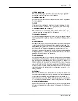
4. INPUT (BAL)
Input channels 1 through 8 have balanced XLR-3-31 type connectors
for connecting microphones. The nominal input level is –60dB to
+4dB. They are wired according to the IEC 268 standard: Pin
1–ground, pin 2–hot (+), and pin 3–cold (–). Phantom powering is
available for condenser type microphones, and it is set using the
PHANTOM MASTER switch.
Input channels 9 through 16 have balanced phone jack connectors.
The nominal input level is –60dB to +4dB. Wiring is sleeve–ground,
tip–hot (+), and ring–cold (–). They can be used with balanced or
unbalanced plugs.
Besides connector type and phantom power, the input circuits for
inputs 1 through 16 are the same. So with an adaptor cable, inputs 9
through 16 can also be used with balanced microphones.
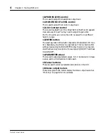
5. POWER switch
This is a push-type power switch. It’s recessed to prevent accidental
operation. Press once to power ON; press again to power OFF.
6. PHONES
This is a stereo (TRS) 1/4" phone jack. A pair of stereo headphones
can be connected here for monitoring. The phones output signal
source is the same as that of the monitor output. The headphone level
is set using the PHONES LEVEL control.
7. MONITOR OUT
These are unbalanced 1/4" phone jacks with a +4dB nominal output
level. They output the monitor signals, and can be connected to the
inputs on a monitor amplifier. The monitor signal source is deter-
mined by the CUE/2TR IN switch and CUE modes. The output level
is set using the MONITOR OUT LEVEL control.
8. AUX SEND
These are unbalanced 1/4" phone jacks with a +4dB nominal output
level. They output the SEND3 and SEND4 signals, and can be used
to feed external effects processors, foldback amplifiers, or multitrack
recording equipment.
SEND3 and SEND4 can be configured as a stereo pair. In this case,
an additional pan control on each input channel and a balance control
on the stereo input channel allows input signals to be panned between
these outputs. See “SEND3-4 Stereo Pair” on page 46 for more details.
Note:
Make sure that the balanced devices you connect to the INPUTs
also use pin 2–hot, pin 3–cold wiring. If they’re wired differently, unde-
sirable phase shifts may occur. Refer to their user manuals for details.
1
2
3
Hot
Cold
Ground
Hot
Cold
Ground
Summary of Contents for Programmable Mixer 01
Page 4: ...ii ProMix 01 User s Guide...
Page 18: ...10 Chapter 1 Touring ProMix 01 ProMix 01 User s Guide...
Page 24: ...16 Chapter 2 User Interface ProMix 01 User s Guide...
Page 36: ...28 Chapter 3 Mixer Functions ProMix 01 User s Guide...
Page 68: ...60 Chapter 6 Groups and Pairs ProMix 01 User s Guide...
Page 74: ...66 Chapter 7 Scene Memories ProMix 01 User s Guide...
Page 96: ...88 Chapter 9 MIDI ProMix 01 User s Guide...
Page 102: ...94 Troubleshooting ProMix 01 User s Guide...
Page 116: ...108 Appendix ProMix 01 User s Guide...
Page 154: ...YAMAHA CORPORATION VS17170 IP 95 01 5000 AP Printed in Japan P O Box 1 Hamamatsu Japan...


