For Service Engineer
Service Information
SI1604009E-002= S20, S10, M20, M10 and D10 installation procedures
25/34
4.3.2
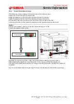
Check and adjust the air pressure
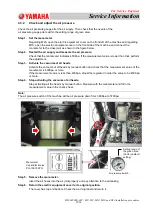
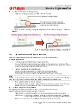
Check the air pressure gauge after the air supply. Then check that the needle of the
air pressure gauge points within the setting range of green area.
Step 1. Set the manometer.
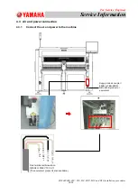
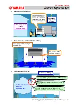
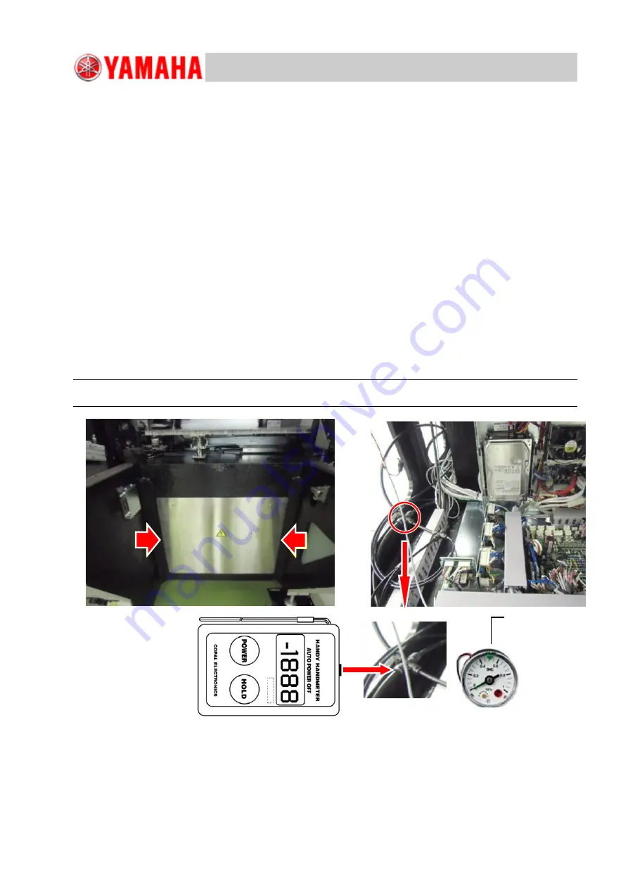
Regarding M20, open the electric equipment cover on the front left of the machine and regarding
M10, open the electric equipment cover on the front side of the machine and connect the
manometer to the cross joint as shown in the figure below.
Step 2. Restart the air supply and measure the air pressure.
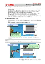
Check that the manometer indicates 450Kpa. If the measurement value is lower than that, perform
the adjustment.
Step 3. Activate the vacuums of all heads.
Activate the vacuums of all heads by manual button and check that the measurement value of the
manometer is 430Kpa or more.
If the measurement value is less than 430Kpa, adjust the regulator in order the value to be 430Kpa
or more.
Step 4. Stop activating the vacuums of all heads.
Stop activating all the heads by manual button. Measure with the manometer and fill in the
measurement value in the check sheet.
Note:
The air pressure switch of the machine will be air pressure down from 368Kpa to 370Kpa.
Step 5. Remove the manometer.
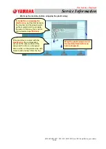
Insert the air hoses into the air joint properly and pay attention to the air leaking.
Step 6. Return the electric equipment cover to its original position.
The cover has top and bottom. Check the warning label and return it.
Setting range of
the green area
(Factory default
setting)
Air pressure switch
Manometer
Copal Electronics:
PG-100-105PG

