For Service Engineer
Service Information
SI1604009E-002= S20, S10, M20, M10 and D10 installation procedures
21/34
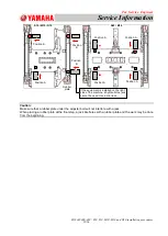
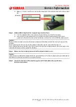
3) Make an
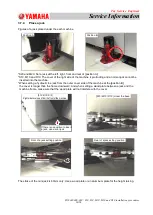
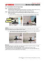
“I” mark on all the lock nut and the thread part of the adjuster bolts with a blue marker
pen.
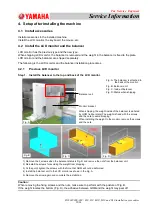
Step 3. [S20 and M20 only] Foot the 2 support legs and lock them.
1)
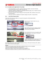
Turn the adjuster bolts in the center by hand until they touch the floor properly.
2)
Set a wrench to the adjuster bolt in the center and rotate it without applying too much
pressure to the wrench until you feel resistance, and lock the lock nut with the other wrench.
Caution:
Make sure that one person checks the pressure intensity of the blots and lock the lock nut to prevent the
variation.
When tightening the lock nut, secure the adjuster bolts with a wrench and rotate the lock nut.
If the contact pressure of the lock nuts in the center is too high, the contact pressure of the lock nuts on the
outer side decreases, which causes the vibration.
Step 4. Make sure that contact pressure of all the adjuster bolts is even.
Caution:
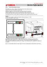
Lastly, make sure that all the adjuster bolts are grounded firmly on the floor by tapping the grounded part of
the bolts with a tool such as wrench or a copper hammer.
Step 5. Check the levelness of the machine again and if it falls within the specification,
fill in the check sheet.
[Example]
Marker pen (Blue)

