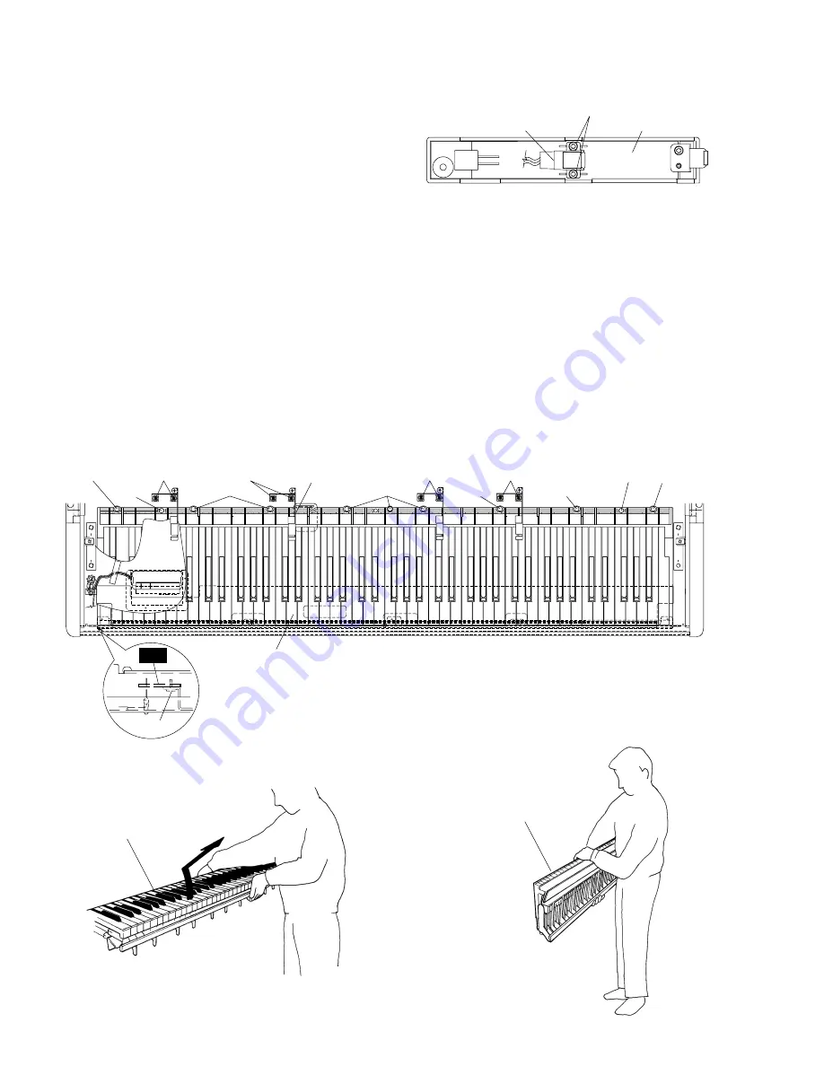
Keyboard assembly
Keyboard assembly
(Fig. 10)
(Fig. 11)
CVP-105
10
7
Power Switch Assembly
7-1
Remove the top board assembly. (See Procedure 1.)
7-2
Remove the key cover assembly. (See Procedure 3.)
7-3
Remove the control panel assembly. (See Procedure 5.)
7-4
Remove the screw marked [53B]. The right end
block can then be removed. (Fig. 6)
7-5
Remove the two (2) screws marked [30C]. The
power switch can then be removed. (Fig. 8)
8
Keyboard Assembly
8-1
Remove the top board assembly. (See Procedure 1.)
8-2
Remove the key cover assembly. (See Procedure 3.)
8-3
Remove the control panel assembly. (See Procedure 5.)
8-4
Remove the right end block. (See Procedure 7-4.)
8-5
Remove the screw marked [53C]. The left end block
can then be removed. (Fig. 6)
8-6
Remove the eight (8) screws marked [52]. The
control panel holders can then be removed. (Fig. 9)
8-7
Remove the two (2) screws marked [74], the nine
(9) screws marked [73]. The keyboard assembly can
then be removed. (Fig. 9)
*
When you take the keyboard unit out of the main
unit, slide it backward and hold the middle of it. Lift
the keyboard unit from the front and take it out of
the main unit as shown in the figures. (Fig. 10 and
Fig. 11)
*
Do not hold both ends of the keyboard.
*
When mounting the keyboard assembly, tighten
screws in this order: [74] and [73].
(Fig. 8)
[30]: Bind Head Tapping Screw-B 3.0 x 8 MFZN2BL (EP600190)
Power switch assembly
<Bottom View>
End block assemly(R)
[30C]
[3]: Bind Head Tapping Screw-B 3.0 x 6 MFZN2BL (EP600230)
[52]: PW Head apping Screw-1 3.5 x 18-10 MFZN2Y (VZ057000)
[73]: Pan Head Screw 5.0 x 25 MFZN2Y (VV040700)
[74]: Bind Head Tapping Screw-1 4.0 x 14 MFZN2Y (EP040230)
(Fig. 9)
Keyboard assembly
[74]
[74]
[52]
[73]
Control panel holder
[73]
[73]
[73]
[73]
[73]
[52]
[52]
[52]
[3c]
PL


